Section F - Transmission
F-5 F-5
9803/9390-2
General Description
Overview
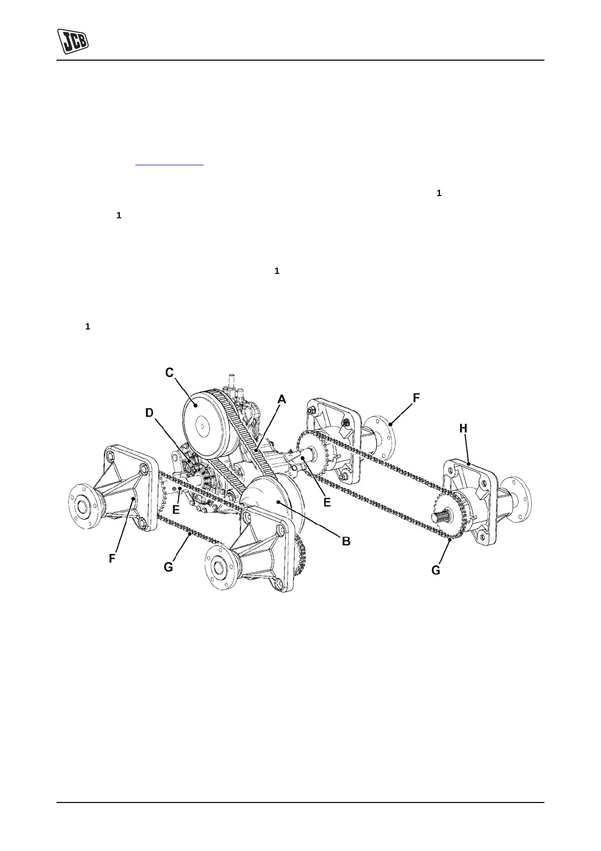
Refer to illustration K Fig 1. ( T F-5)
Power is transferred from the engine to the transaxle via an
‘automatic’ continuously-variable transmission system
(CVT system). The system basically comprises of a heavy-
duty drivebelt 1-A running between two variable pulleys
(one attached to the engine, the other to the transaxle drive
shaft). The pulley-walls (sheaves) move apart or together,
depending on engine speed.
The engine mounted pulley or ‘driver clutch assembly’ 1-B
is driven by the engine crankshaft. Varying centrifugal
force causes rollers within the unit to move outward or
inward. This causes a varying separation of the pulley-
walls. Accordingly, the transaxle mounted pulley or ‘driven
clutch’ 1-C also varies due to the belt and its in-built clutch
spring. As the effective ‘diameter’ of the driver clutch pulley
increases, the driven pulley becomes smaller. The
transmission drive ratio therefore varies.
The transaxle gearbox unit 1-D operates in Neutral,
Forward and Reverse, depending on the position of the
gear selector. When Forward or Reverse is selected,
power from the transaxle is transferred to the centre wheel
axles 1-F through couplings 1-E.
Drive from the centre wheel axles is transferred to the rear
wheel axles 1-H by means of drivechains 1-G. The
drivechains can be adjusted (tightened or slackened) by
means of adjusters.
The transaxle unit incorporates a differential lock which is
operated by a lever.
Fig 1. CVT System and Drivetrain
Transaxle
Within the transaxle unit, drive is transferred from the input
shaft to two output shafts, through a chain-driven reduction
gear, final gear, and differential.
Differential lock is engaged and disengaged by means of a
lever assembly.


 To Next Page