Section H - Steering
H-7 H-7
9803/9390-2
Rack and Pinion Steering Gear
Removal and Replacement
1 Apply the park brake and chock the rear wheels.
Disconnect the battery.
!MWARNING
A raised and badly supported machine can fall on you.
Position the machine on a firm, level surface before
raising one end. Ensure the other end is securely
chocked. Do not rely solely on the machine hydraulics
or jacks to support the machine when working under
it.
Disconnect the battery, to prevent the engine being
started while you are beneath the machine.
GEN-1-1
2 Raise and properly support the machine. Remove the
front roadwheels, see Section 3 - Routine
Maintenance.
Tie-Rod Outer Ball Joints
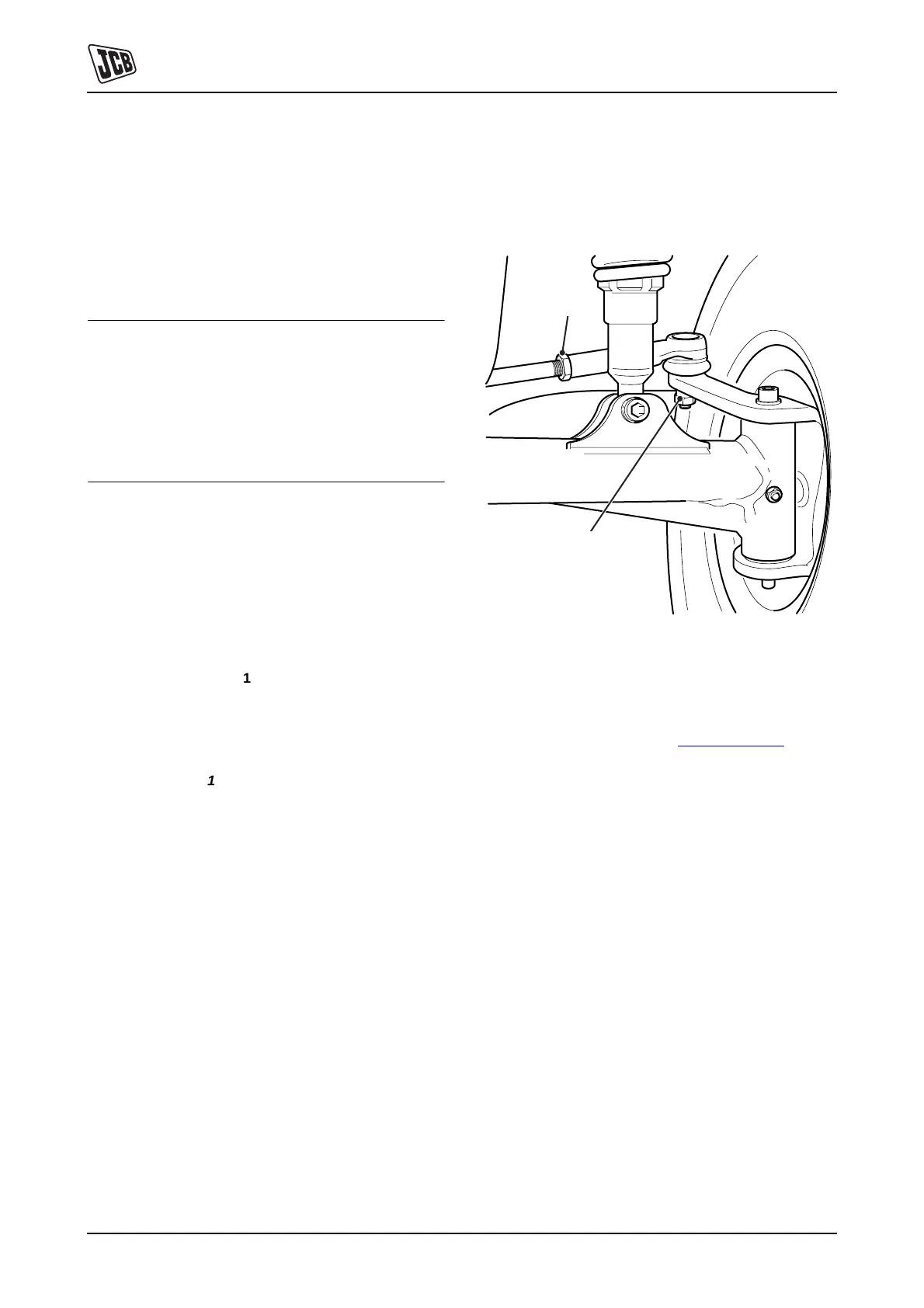
3 Disconnect the steering tie-rod outer ball joints from
the kingpins:
a Remove the nut 1-A.
b Disconnect the ball joint (track rod end) from the
kingpin. If necessary, use a ball joint separator.
Note: If replacement of the track rod end is required,
loosen the locknut 1-B (a quarter of a turn) and unscrew
the rod end from the tie-rod.
Fig 1. Tie-rod Outer Ball Joint
Universal Joints
4 Loosen the bolt 2-A of the lower universal joint, which
connects the steer rack pinion shaft to the steering
column intermediate shaft, K
Fig 2. ( T H-8)
Note: To prevent incorrect orientation of the universal
joints, the intermediate shaft will only allow the UJ bolts to
be inserted when in the correct position - observe when
dismantling.
Important: When installing the steering rack and column,
tighten the UJ bolts last.
B
A


 To Next Page