Installation—Installing the FC-2000 67
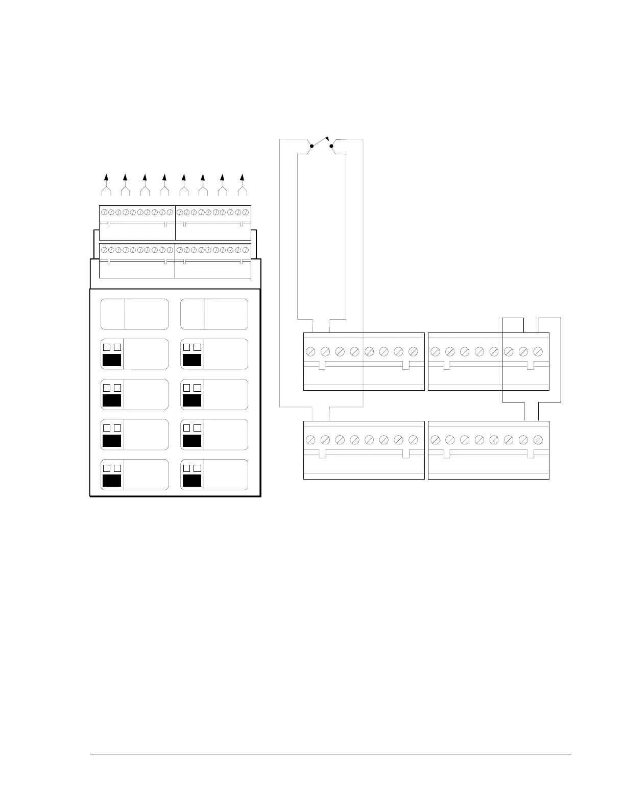
Figure 50: Connection Diagram For Remote Presignal Inhibit,
All Call (General Alarm), Emergency Alert, Acknowledge,
Signal Silence and System Reset Switches (Style D)
Use circuit
D
for All-Call (General Evacuation),
E
for Emergency Alert,
F
for Acknowledge,
G
for Signal Silence, and
H
for Reset.
A+A- A+A- A+A- A+A-
A B C D E F G H
A+A- A+A- A+A- A+A-
A
Presignal Inhibit
B
(Standard Zone)
C
(Standard Zone)
D
(Standard Zone)
E
Emergency Alert
F
Acknowledge
G
Signal Silence
H
Sytem Reset
B+ B-
A+ A-
izmswch2
Jumper all unused
circuits as shown.
Presignal Inhibit
Switch
Style D
INITIATIN G
ZONE
RED - ALARM
YELLOW- TROUBLE
DISPLAY PROGRAM
MODULE
TYPE
LAMPS
SWITCH
INIT IA T IN G
ZONE
RED - ALARM
YELLOW- TROUBLE
DISPLAY PROGRAM
MODULE
TYPE
LAMPS
SWITCH
 Loading...

