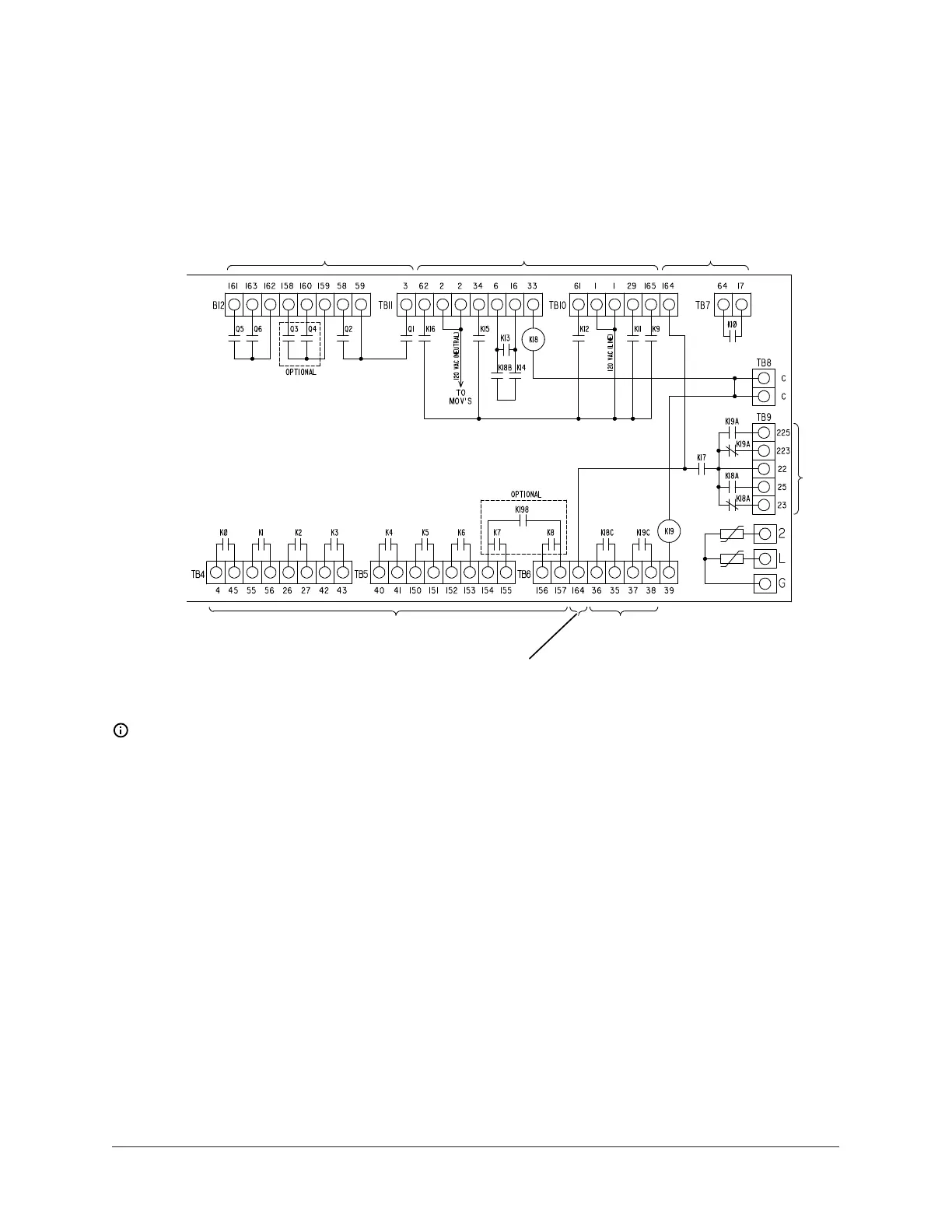
Figure 7: OptiView control panel I/O board (031-03631) details
035-26576-000
REV D, SHT. 3
Triac Closures
(See Notes 1, 5 & 6)
120 VAC Output Contacts
(See Notes 1, 4 & 5)
Contact Closures
(See Notes 1, 5 & 7)
Contact Closures
(See Notes 1, 4 & 5)
Contact Closures
(See Notes 1, 5 & 7)
Contact Closures
(See Notes 1, 3 & 5)
Note: See detail A of Figure 5 for J19 details.
Wiring notes
1. Field wiring must be in accordance with the NEC and all other applicable codes and
specifications.
2. Device contact reating must be 5 mA at 115 VAC.
3. The contact rating is 5 A resistive at 120 VAC or 240 VAC.
4. The contact rating is 5 A resistive at 250 VAC and 30 VDC, 2 A inductive (0.4 PF) at 250 VAC and
30 VDC.
5. The 115 VAC field-connected inductive loads include the relay coil, motor starter coil, and
similar items. Each of these inductive loads must have a transient suppressor wired in parallel
with its coil, which is physically located at the coil. Spare transient suppressors and control
circuit fuses are supplied in a bag attached to the keypad cable camp in the left corner of the
control panel.
23Unit Wiring and Field Connections for YZ Centrifugal Chiller with Magnetic Bearing Controller