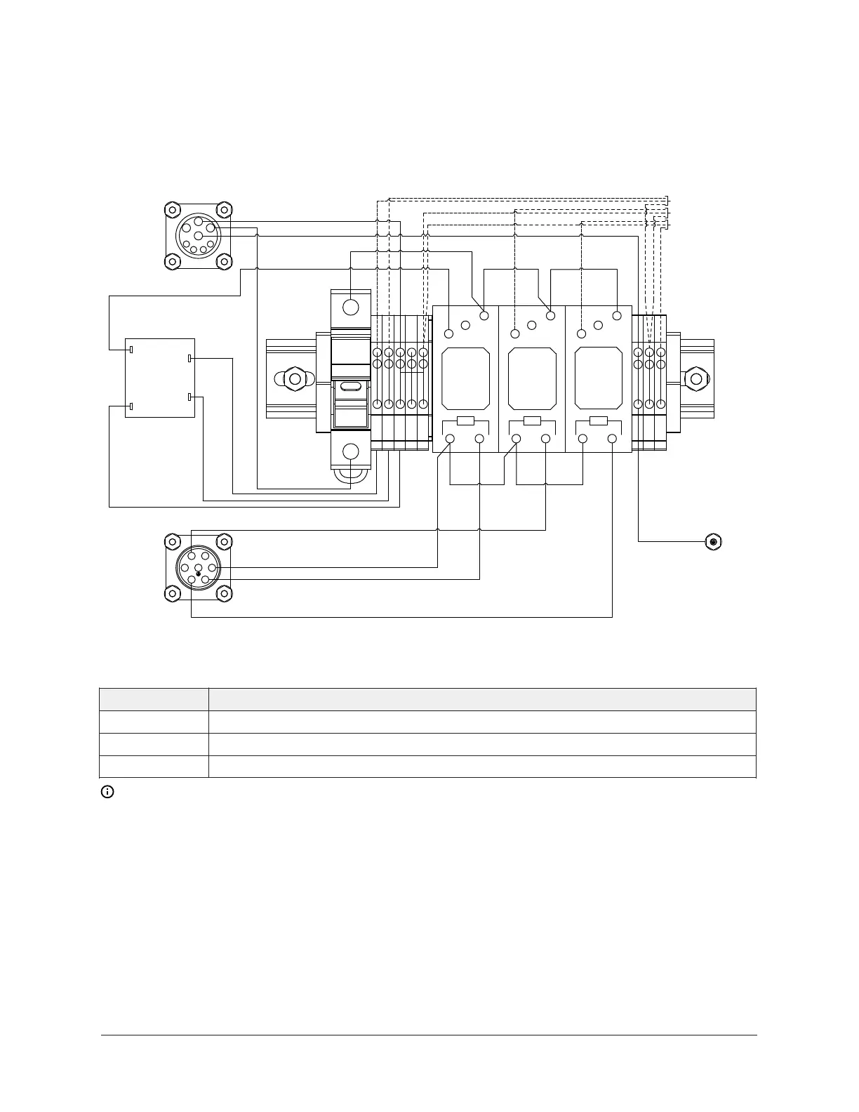
Purge panel enclosure and schematics for 50 Hz
Figure 23: Purge panel enclosure and schematics for 50 Hz
Front View of the Purge Panel
Item Description
K120 Purge Compressor Relay
K121 Purge Pump Relay
K122 Regen Tank Relay
Note:
1. Install 8A class CC fuse between Terminal 2 and Terminal 7 on the LV side.
2. Install 5A class CC fuse between Terminal 2 and Terminal 7 and 5-8 on the HV side.
Unit Wiring and Field Connections for YZ Centrifugal Chiller with Magnetic Bearing Controller40