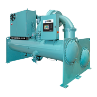
UPS circuitry wiring diagram
Figure 17: UPS circuitry wiring diagram
NON-CRITICAL POWER 120VAC
Condenser Level Valve
HG By-Pass Valve
UPS LINE/CHARGING
UPS INVERTER
UPS FAULT
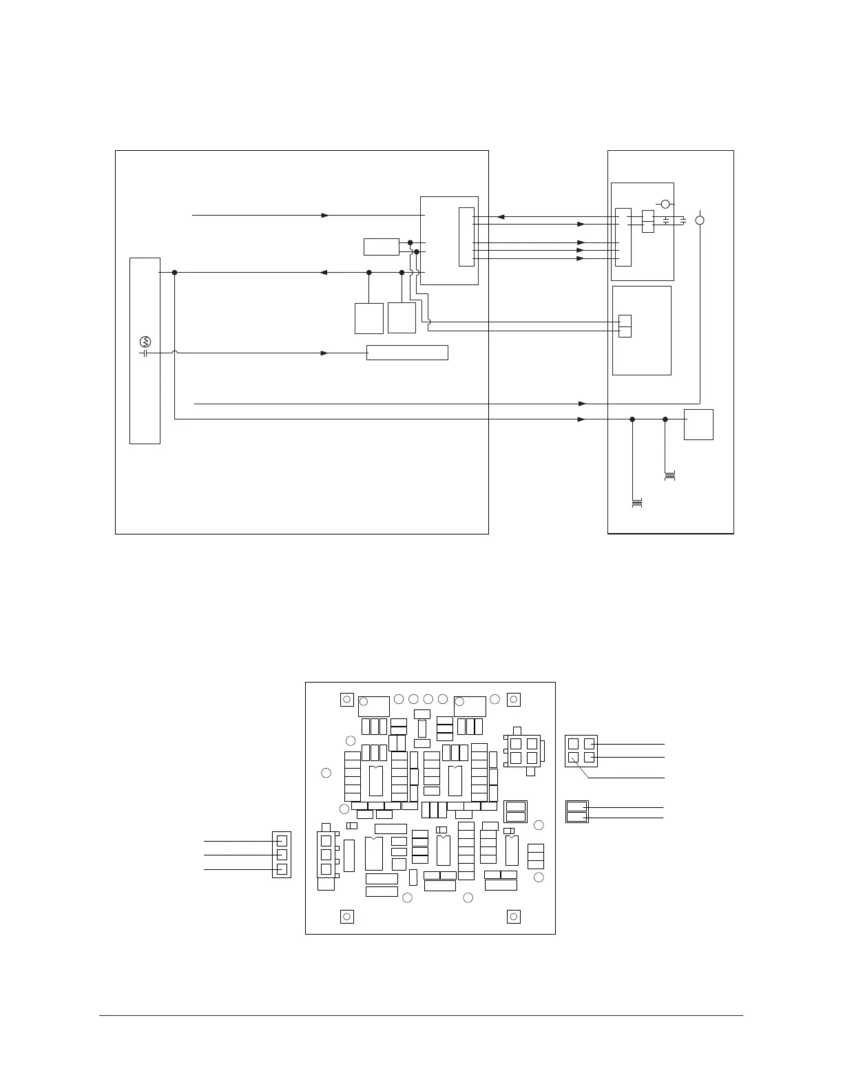
OptiView control panel stall detector board assembly
Figure 18: OptiView control panel stall detector board assembly
031-02418-999
REV E, SHT.3
To
Stall Detector
Discharge Pressure
Unit Wiring and Field Connections for YZ Centrifugal Chiller with Magnetic Bearing Controller34