DP350 User's Manual
- 46 -
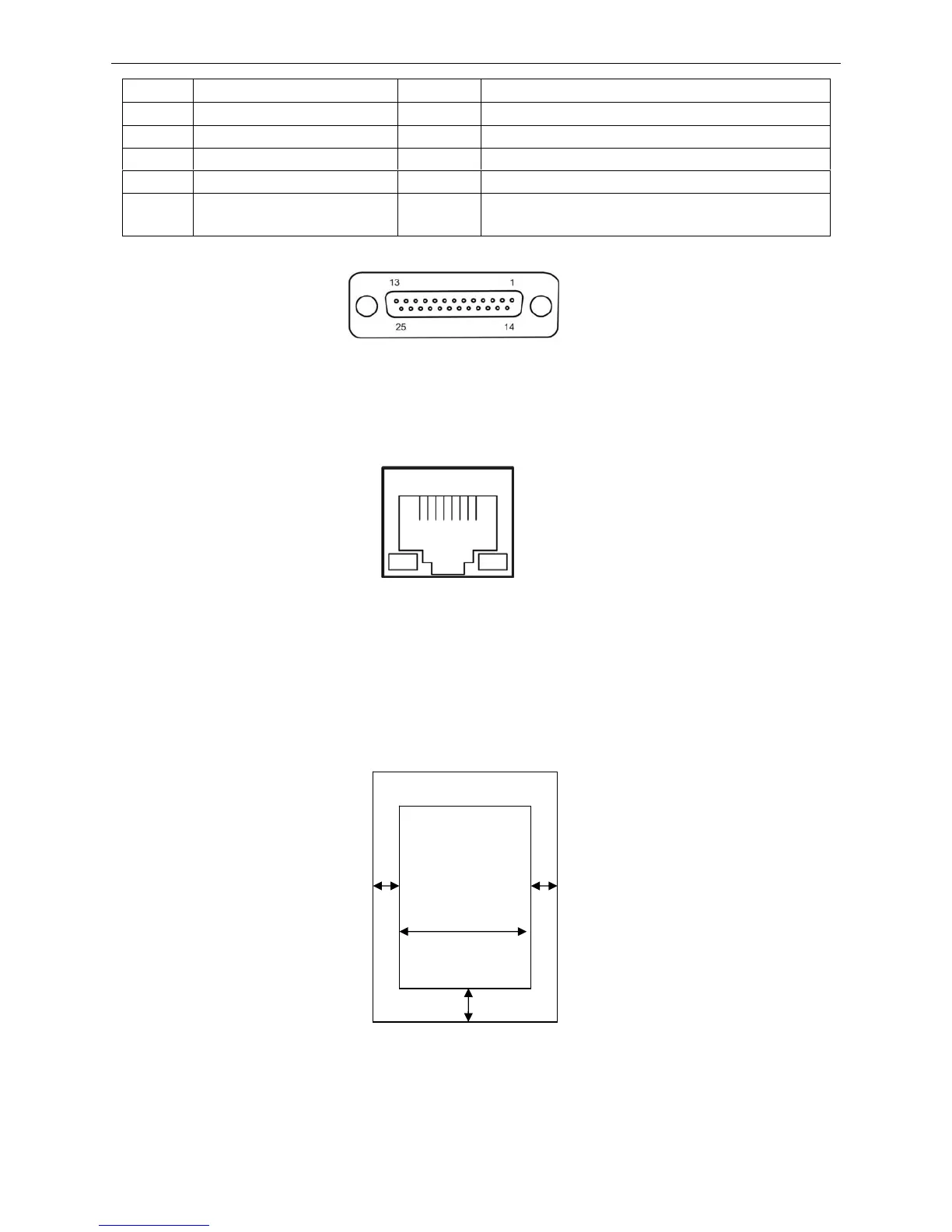
A.2.4 Ethernet Interface
10/100Base-T Ethernet interface can connect to 10/100M Ethernet.
A.3 Printable Area
Note: 1. To assure the print quality, please make sure the print contents are within the printable
area.
2. If the print contents exceed the printable area, the print head may be damaged.
Cut Sheet:
A: The top margin ≥ 8.0 mm.
B: The right/left margins ≥ 3.0 mm.
However, the maximum printable width is 203.2 mm.
C: The bottom margin ≥ 9.0 mm.
Pin No. Signal Direction Description
1 Frame Ground (FG)
—
Printer’s chassis ground
2 Transmitted Data (TXD/SD) Out Printer has transmitted serial data
3 Received Data (RXD/RD) In Printer has received serial data
7 Signal Ground (SG)
—
Return path for data control signals
20 Data Terminal Ready (DTR) Out
Positive when the printer is ready to receive data,
and negative when the printer is not ready
Figure A-3 Serial interface connector pin number
Figure A-4 Ethernet interface
≥ 3 mm
≥ 8 mm
≥ 9 mm
≥ 3 mm
Max. 203.2 mm
Printable area