8-10
8.3 Performance Check
yyyy
yyyy
8
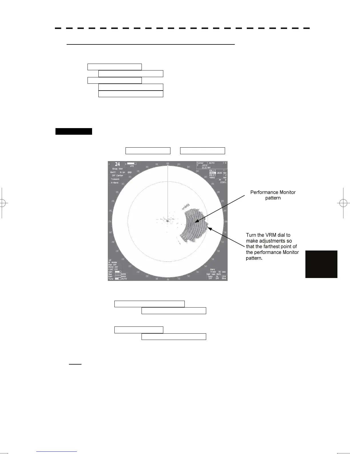
[IV] Check of the Performance Monitor (MON Display)
Displays the performance monitor status.
* Transmitter System Transmitter system attenuation value check.
Attenuation Value
* Receiver System Receiver system attenuation value check.
MON Pattern Range
Attenuation Value
Turn the [VRM] dial to make adjustments so that the farthest point of the performance monitor pattern.
The attenuation value of receiver system is displayed.
Procedures 1. Turn the [VRM] dial to make adjustments so that the farthest point of
the performance monitor pattern.
The Attenuation Value of *Receiver System is displayed.
2. Check the attenuation value.
* Transmitter System
Attenuation Value
Normal operating range : -7.0dB<indication value<+2.0dB
* Receiver System
Attenuation Value
Normal operating range : -3.0dB<indication value<+3.5dB
Note:
If Receiver System Attenuation Value display is under -3 dB or Transmitter System Attenuation
Value display is under -7 dB with the performance monitor test, radar should be checked by service
engineer. This means that the TX/RX unit may be faulty. Consult with the near-by dealer or our
sales department.
 Loading...


