8-21
8.4.3 Replacement of Motor
Caution: Replacement of motor must be made by specialized service personnel.
For details, refer to Service Manual.
Motor Replacement Procedure for Scanner Unit NKE-1130
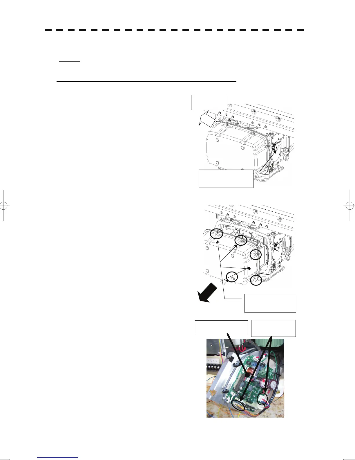
(1) Before starting part replacement work, turn off the
safety switch of the scanner unit.
The safety switch is located on the rear (stern) side.
Remove the cover and turn off (to the lower side) the
safety switch.
(2) Loosen the hexagonal bolts and remove the cover on the
both sides
(3) Remove the cover on the right (starboard) side and
loosen the four screws (M4) to remove the driver
unit, which has the motor driver circuit board on its back
side.
Disconnect the cables connecting the motor to the motor
driver circuit board.
Bow side
Turn off the safety
switch.
Remove the eight
hexagonal screws.
Driver circuit board
Disconnect the
cables.
 Loading...


