8-25
Motor Replacement Procedure for Scanner Unit NKE-2103
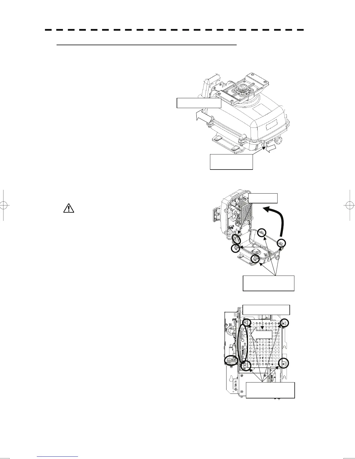
(1) Before beginning work, turn off the safety
switch on the bottom of the scanner unit.
(2) Loosen the hexagonal bolts (four bolts) and open the upper
cover until the stopper of the stay operates.
When closing the upper cover, release the stay stopper and
then tighten the cover.
(3) Loosen the screws (four M4 screws), remove the
transmitter-receiver unit cover, and remove the cables connected to
the transmitter-receiver unit (ten cables). Slide the cover of the
transmitter-receiver unit to remove it.
Stay
Loosen the four
hexa
onal bolts.
Bow direction
Turn off the
safet
switch.
Slide the cover.
Loosen the four
screws.
 Loading...


