1-21
CFQ-6912
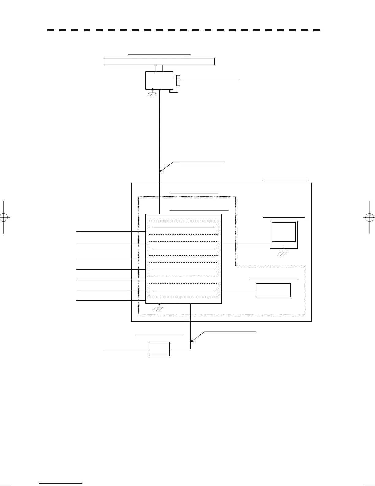
MAX φ14.5 (JRC SUPPLY)
19 CORES COMPOSITE CABLE
NJU-85 PERFORMANCE MONITOR
NKE-2103-6 SCANNER UNIT
NCM-878 CONTROL UNIT
NCE-5171 OPERATION UNIT
NDC-1477 RADAR PROCESS UNIT
NCD-4590 DISPLAY UNIT
0.6/1kV-DPYC-6
CFQ-5436-5
MAX φ10 (JRC SUPPLY) 5m
NBA-5111 POWER SUPPLY
GYRO
LOG(200P)
250V-TTYCS-4
250V-TTYCS-1
250V-MPYCYS-7
250V-DPYCYS-1.5
250V-TTYCS-1
GPS
SHIP'S MAIN
AC100/110/115V 50/60Hz 1φ
AC220/230/240V 50/60Hz 1φ
H-2695111153 MAX φ18
(JRC SUPPLY, OPTION)
INTERSWITCH
AIS
LOG(NMEA)
(JRC SUPPLY) 5m
(OPTION)
NCT-59A GYRO INTERFACE UNIT
NQA-2103 AIS PROCESS UNIT
NDB-34A PLOTTER CONTROL UNIT
NOTE: Eliminating the interference on frequencies used for marine communications and navigation due to
operation of the radar.
All cables of the radar are to be run away from the cables of radio equipment.
(Ex. Radiotelephone. Communications receiver and direction finder, etc. )
Especially inter-wiring cables between scanner unit and display unit of the radar should not be run parallel
with the cables of radio equipment.
DC24V
JRC LAN
LAN CABLE H-7ZCNA0483
(JRC SUPPLY, OPTION)
MONITOR UNIT:
NWZ-170,HATTELAND,
MELFORD or ISIC
NCA-877WA ARPA PROCESS UNIT
(OPTION)
Fig. 1.14 General System Diagram of JMA-5912-6 RADAR
 Loading...


