– 30 –
1) Loosen bed cover setscrews
to remove bed cover
.
2) Adjust the standard feed adjusting dial to "0".
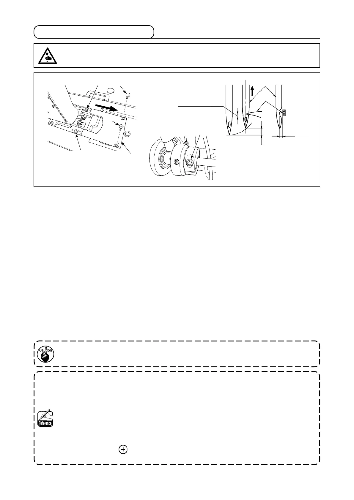
3) Loosen hook driving shaft set collar clamping screw
, and turn the handwheel counterclockwise to
make the needle bar ascend by 2.3 mm from the lowest position of its stroke.
● For the PLC-2710, -2710-7, -2760, -2760-7 and -2765
4) In the state described in 3), align blade point
of the hook with the center of needle
, and tighten
hook driving shaft set collar clamping screw
. At this time, a clearance of 1.5 mm is provided between
the blade point of the hook and the top end of the needle eyelet.
● For the PLC-2760L
4) In the state described in 3), align blade point
of the hook with the center of needle
, and tighten
hook driving shaft set collar clamping screw
.
At this time, a clearance of 2.0 mm is provided between
the blade point of the hook and the top end of the needle eyelet.
5) Loosen setscrews
and
of the hook driving shaft saddle on the top face of the bed. Adjust the clear-
ance between the blade point of the hook and the needle to 0.05 to 0.1 mm by moving the hook driving
shaft saddle to the right or left to change its position. Then, tighten setscrews
and
.
6) Align the largest scale mark of the standard feed adjusting dial with the marker dot on the machine arm.
Check to be sure that the blade point of the hook does not come in contact with the needle.
The operation panel could come in contact with the thread stand when tilting the machine head.
To protect the relevant parts from contact, shift the thread stand to a position at which the thread
stand does not interfere with the control panel.
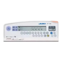
[Only for the PLC-2710-7 and PLC-2760-7]
To check the needle bar position as described in the aforementioned 3) [i.e., "...the needle bar
ascend by 2.3 mm from the lowest position of its stroke"], you may use the display of the main
shaft rotation angel under the "machine head adjustment mode" of the SC-922.
The needle bar goes up by 2.3 mm by advancing the angle of rotation of the main shaft by 25 º
(upper shaft angle = 205 º) from the value displayed when the needle bar is in its lower end under
the "machine head adjustment mode".
(When the needle bar ascends by 2.3 mm from its lowest
position of its stroke, the main shaft rotation angle is 25 degrees of an angle.)
* In the case of adjusting the needle-to-hook relation under the "machine head adjustment
mode", do not press switch.
Refer to "3-2. Adjusting the machine head (PLC-2710-7, 2760-7)" p.13.
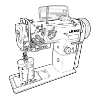
WARNING :
To protect against possible personal injury due to abrupt start of the machine, be sure to start the
following work after turning the power off and ascertaining that the motor is at rest.
4-4. Needle-to-hook relation
0.05 to
0.1 mm
1.5 mm
(2760L : 2.0mm)
2.3 mm
 Loading...