o Whenthe SC-220panel is used, when pattern No. 3 is selected the number
of
stitches for start reverse
stitching and
finish
reverse
stitching isindicated. 4
When4 is set as shown in Fig.
44,
the stitching is
done as shown in Fig. 4-6.
Notes) 1. The number of reversestitches is the same
in
both
forward
and
reverse.
2. Insert a screwdriverinto the groove shown
by the arrow to changethe number of
stitches.
Fig. 4-6
(7)
Selection
of
automatic presser foot lifting function
The presser foot is operated automatically by a solenoid without need to use the lifter lever, when the automatic
presser foot lifting function is selected.
Make
thisselection
using
a combination of
SW5-1
(FL ON)and
SW5-2
(FL
PW)
(referto Table4-6).
Table
4-6
FL
ON
FL
PW
Control applied
OFF
OFF
Operation independent
of
thread trimming and sewing machine operation.
When there is no Auto-lifer, use these settings.
OFF
ON
Disable
ON
OFF
Auto-lifter control (raisedautomatically for 60 secondsafter thread trimming).
ON
ON
Auto-lifter control (after thread trimming,raisedfor 10 minutes unless there
is some input from the switches including the FL SWor L SW.)
In addition, the aforementioned combinations of the switches can also control the valvesby
setting SW2-4(PNEUF) to its ON position.
ON : Valvesare controlled pneumatically or hydraulically. (The signalretaining the
presser foot is set to non-switching
output
state.) DC34V
OFF : Valvesare controlled by solenoid. (The signal retaining the presser foot is set to
ON/OFF switchingoutput state in 2.5 ms intervals.)
(Caution) When
the
solenoid controls
the
valves, be sure
to
set
the
PNEUF
to
its
OFF
position.
If it is
set
to
its ON
position,
the
solenoid
will
be
burnt
out.
In addition, when pneumatic or hydraulic valvecontrol is made, be sure to follow one
of
the
procedures mentioned below. And be sure to add a diode on the outside
of
the circuit board
or add a jumper wire on the circuit board.
If
you do
not
add one
of
these, the transistor
circuit board might be injured.
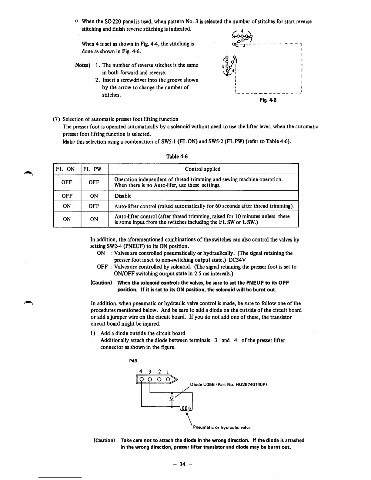
1) Add a diode outside the circuit board
Additionallyattach the diode between terminals 3 and 4
of
the presserhfter
connector as shown in the figure.
P48
4 3 2 1
Q O O O
Diode
U05E
(Part
No.
HG26740140P)
7
i
\
Pneumatic
or
hydraulic
valve
(Caution)
Take
care
not
to
attach
the
diode
in
the
wrong
direction,
if
the
diode
is
attached
in
the
wrong
direction,
presser
lifter
transistor
and
diode
may
be
burnt
out.
-
34
-