4-6. Production
control
system and needle-up
stop
switch functions
JPS
1
IbiJJ
1
0119]
>8
-
llOi^l
Fig.
4-30
I I
t2-SJ
CZH
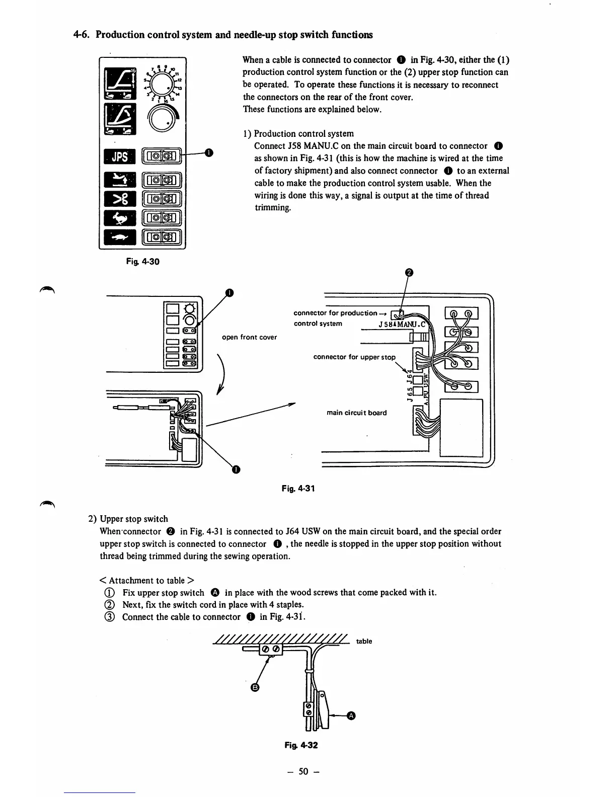
When
a cableis connected to connector O InFig. 4-30, either the (1)
production control system function or the (2) upper stop function can
be operated. To operate these functions it is necessary to reconnect
the
connectors
on
the
rear
of
the
front
cover.
These functions are explained below.
1) Production control system
Connect
J58
MANU.C
on
the
main
circuit
board
to
connector
O
as shown in Fig. 4-31 (this is how the machine is wired at the time
of factory shipment) and also connect connector O to an external
cable to make the production control system usable. When the
wiringis done this way, a signalis output at the time
of
thread
trimming.
open
front
cover
connector
for
production
-
control
system
J
SSAMANU.C
connector
for
upper
stop
main
circuit
board
Fig. 4-31
2) Upper stop switch
When
connector O in Fig. 4-31 isconnected to J64
USW
on the main circuit board, and the special order
upper stop switch is connected to connector O , the needle is stopped in the upper stop position without
thread being trimmed during the sewing operation.
<
Attachment
to
table
>
(T)
Fix
upper
stop
switch
O in
place
with
the
wood
screws
that
come
packed
withit.
@ Next,fix the
switch
cordin
place
with4
staples.
(3) Connectthe
cable
to connector O in
Fig.
4-31.
table
Fig.
4-32