2) Control box mounting
(1)
Place
the newcontrolbox in the correctbox mountingpositionon the top surfaceof
sewing
machine
head and mount it with the 2 accessoryscrews(Fig. 4-21).
(2) Bringthe cord to the PSCbox position alongthe wiringroute in Fig. 4-23.
(3) Openthe
PSC
box front
cover.
Connectthe type of connector
specified
for the type of box beingmounted
(SC-20
J67
2P,
SC-120
•
SC-220
J60
16P,
SC-320
J61
20P.)
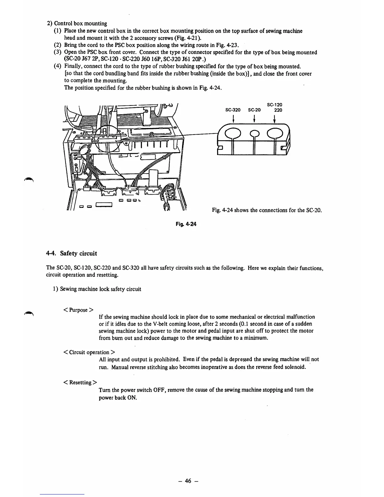
(4) Finally, connectthe cord to the type of rubber
bushing
specified
for the type of box
being
mounted.
[so
that the cord
bundling
band
fits
inside
the
rubber
bushing
(inside
thebox)], and
close
the front
cover
to complete the mounting.
The positionspecifiedfor the rubberbushingisshownin
Fig.
4-24.
Fig.
4-24
SC-320
SC-20
SC-120
220
I < 1
O Q O
Fig. 4-24 shows the connections for the SC-20.
4-4.
Safety
circuit
The SC-20,SC-120,SC-220and
SC-320
all have safety circuits such as the following. Here we explain their functions,
circuit operation and resetting.
1) Sewingmachine lock safety circuit
< Purpose >
If the sewing machine should lock in place due to some mechanical or electrical malfunction
or
if
it idles due to the V-belt coming loose, after 2 seconds (0.1 second in case
of
a sudden
sewingmachine lock) power to the motor and pedal input are shut
off
to protect the motor
from burn
out
and reduce damage to the sewing machine to a minimum.
< Circuit
operation
>
All input and
output
is prohibited. Even if the pedal is depressed the sewing machine will not
run. Manualreversestitching alsobecomes inoperative as does the
reverse
feed solenoid.
< Resetting >
Turn the power switch OFF, remove the cause of the sewingmachine stopping and
tum
the
power
back
ON.
-
46
-