4) If power is turned ON while pedal is depressed
If the power switch is turned ON while the pedal is depressed, if the needle is down it goes to the up position,
if up it just stays there. Operation is the same as when the pedal is in neutral.
< Resetting > Return the pedal to neutral, then depress it again and the sewing machine will return to
normal
operation
5) Reverse feed solenoid safety circuit
If the manual reverse stitching switch is held ON continuously for 12 seconds or more, power to the reverse
feed solenoid is shut off, except that automatic start and finish reversestitching proceed normally even while
this safety circuit is operating. If thread trimming takes place while this switch is held ON continuously, power
to
the
reverse
feed
solenoid
is
shut
off.
<Resetting> Turning the
manual
reverse
stitching
switch
OFF
releases
the safetycircuit.
6) Auto-lifter safety circuit
After the thread is trimmed, the
presser
foot is
raised
by the automatic
lifting
function,but if it staysup for
1minute, the
power
to the
presser
foot
lifting
solenoid
is
automatically
shut offand the
presser
foot is
lowered.
However,
asdiscussed in the explanation of dip switches FLONand
FLPW
on Item 4-2-3)-(7), when both FLON
and
FLPW are ON it stays up.
< Resetting > Afterthe presser foot is
lowered
the
system
returnsto the initialcondition,and the
presser
foot can be raised at any time by thread trimming or the knee switch.
7) Needle position detector loose connector safety circuit
If this needle position detector connector becomes disconnected
and then the power is turned ON, the
motor
will not operate.
< Resetting > Turn the power OFF, plug the connector in
correctly as shown in Fig. 4-26 and turn the
power
back
ON.
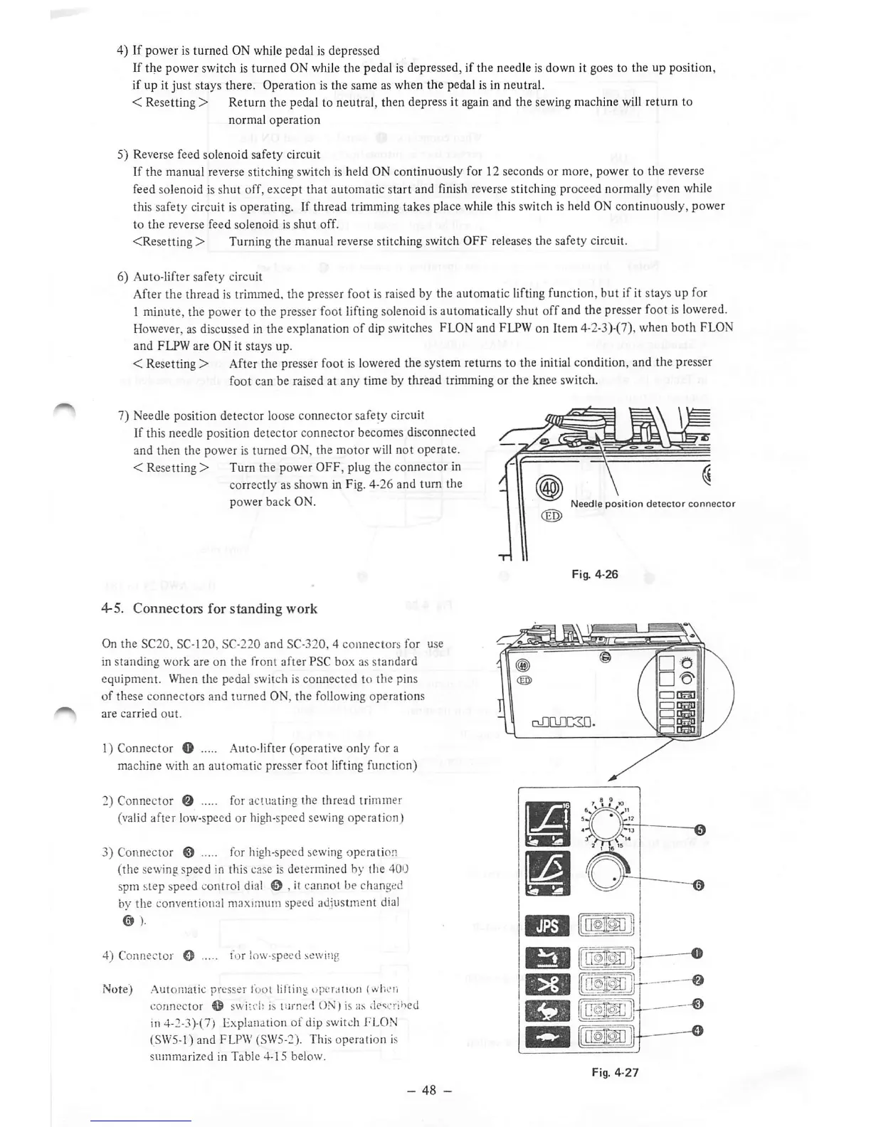
4-5. Connectors for standing work
On
the
SC20,
SC-120,
SC-220
and
SC-320,4
connectors
for
use
in standing work are on the front after PSC box as standard
equipment. When the pedal switch is connected to the pins
of these connectors and turned ON, the following operations
are
carried
out.
1) Connector O Auto-lifter (operative only for a
machine with an automatic presser foot lifting function)
2) Connector Q for actuating the thread trimmer
(valid after low-speed or high-speed sewing operation)
3) Connector @ for high-speed sewing operation
(the sewing speed in this case is determined by the 40U
spm
step
speed
control
dial
0 , it cannot be
changed
by the conventional maximum speed adjustment
dial
0 ).
4) Connector O for low-speedsewing
Note)
Automatic presser fool lifting operation (when
connector
O
switchis
turned
ON)
is as .le<ic!ibed
in 4-2-3)-(7) Lxplanation of dip switch FLON
(SW5-1) and FLPW (SW5-2). This
operation
is
summarized
in
Table
4-15
below.
Needle
position
detector
connector
Fig.
4-26
oJlQflCSD.
•
ED
Fig.
4-27
 Loading...


