r
Fig.
5-5
O
Fig.
5-6
Driver
m
Fig.
5-7
Fig.
5-7
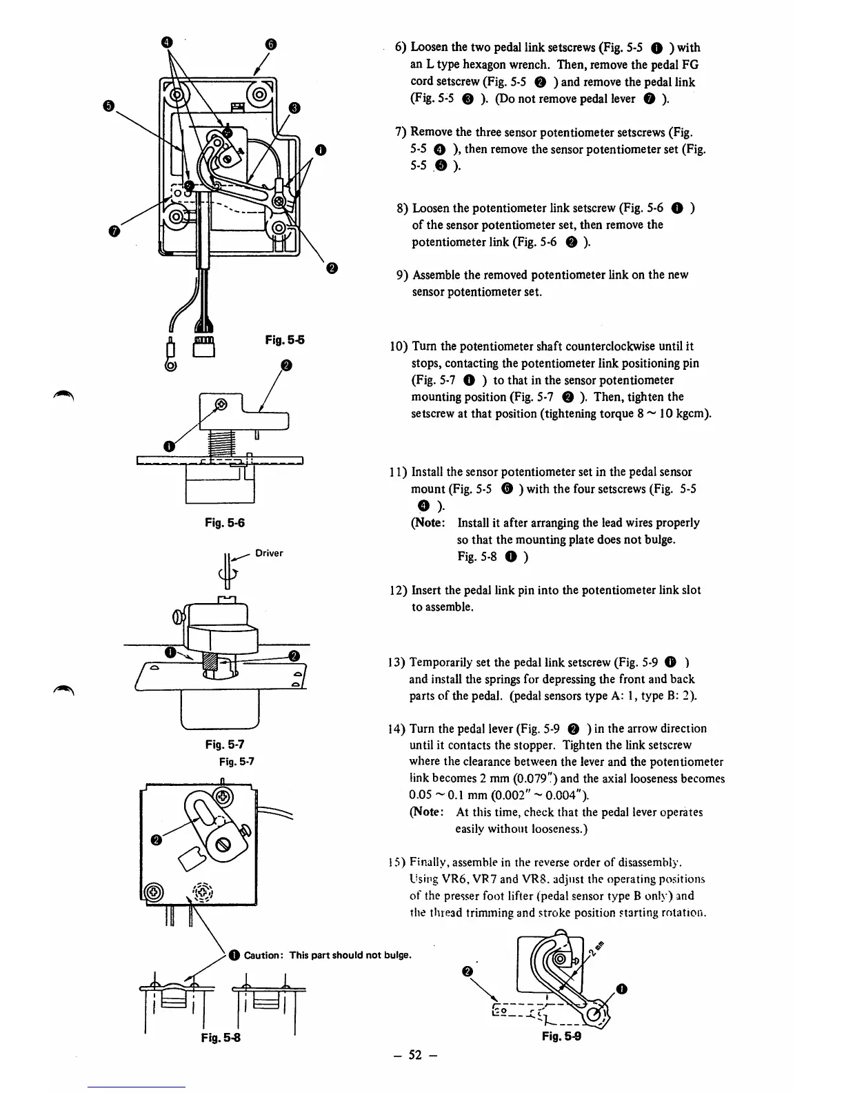
6)
Loosen
the two pedallink
setscrews
(Fig.
5-5
O ) with
an L type hexagon wrench. Then, remove the pedal FG
cord setscrew (Fig. 5-5 O ) and
remove
the pedallink
(Fig.5-5 0 ). (Donot
remove
pedallever O ).
7) Remove the three sensor potentiometer setscrews (Fig.
5-5 O )»then removethe sensor potentiometer set (Fig,
5-5
.0
).
8) Loosenthe potentiometer link setscrew(Fig. 5-6 O )
of the sensor potentiometer set, then remove the
potentiometer link (Fig. 5-6 0 ).
9) Assemblethe removed potentiometer link on the new
sensor
potentiometer
set.
10) Turn the potentiometer shaft counterclockwise until it
stops, contacting the potentiometer link positioning pin
(Fig. 5-7 O ) to that in the sensor potentiometer
mounting position (Fig. 5-7 0 ). Then, tighten the
setscrew at
that
position (tightening torque 8 ~ 10 kgcm).
11) Install the sensor potentiometer set in the pedal sensor
mount
(Fig.
5-5
0 ) with the four
setscrews
(Fig.
5-5
o).
(Note: Install it after arranging the lead wires properly
so
that
the
mounting
plate does
not
bulge.
Fig. 5-8 O )
12) Insert the pedal link pin into the potentiometer link slot
to
assemble.
13) Temporarily set the pedallink
setscrew
(Fig.
5-9
© )
and install tlie springs for depressing the front and back
parts of the pedal, (pedal sensors type A: 1, type B: 2).
14) Turn the pedal lever (Fig. 5-9 0 ) in the arrow direction
until it contacts the stopper. Tighten the link setscrew
where the clearance between the leverand the potentiometer
link
becomes
2 mm(0.079")and the
axial
looseness
becomes
0.05 ~ 0.1 mm(0.002"~ 0.004").
(Note: At this time, check that the pedal leveroperates
easily without looseness.)
1.^)
Finally,
assemble in
the
reverse
order
of
disassembly.
Using
VR6,
VR7 and VR8. adjust the operating positions
of
the presser foot lifter (pedal sensor type B only) and
the thread trimming and stroke position starting rotation.
O Caution: This part should not bulge.
©
0
^2.
Fig.
5-8
Fig.5-9
-
52
-
 Loading...


