– 32 –
Select function No. 12 in the steps 1 to 3 of the operation procedure for function
settings.
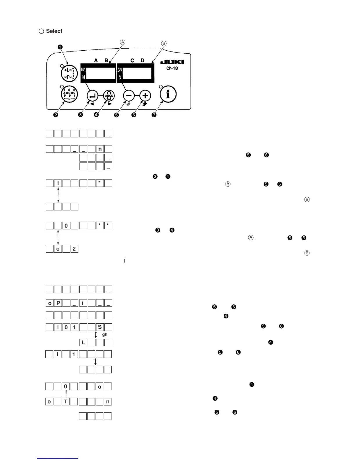
Select the items of “End”, “in” and “ouT” with keys and .
[When “in” is selected]
Use the key or to specify the display No. after the display No. of input function
setting connector appears on the indicator
A
. Use the key or to select the
function of the connector pin corresponding to the display No.
The function code and abbreviation are alternately displayed on the indicator
B
.
(Refer to the attached table for the relationship between display Nos. and
connector pin arrangement.)
[When “ouT” is selected]
Use the key or to specify the display No. after the display No. of output
function setting connector appears on the indicator
A
. Use the key or to
select the function of the connector pin corresponding to the display No.
The function code and abbreviation are alternately displayed on the indicator
B
.
(Refer to the attached table for the relationship between display Nos. and
connector pin arrangement.)
* Example) Thread trimming function selected for display No. i01 (CN44-4) of input function setting connector
1. Select function No. 12 in the steps 1 to 3 of the operation procedure for
function settings.
2. Select the items of “in” with keys and .
3. Select display No. “i01” using the key .
4. Select the thread trimming function, “TSW” with keys and .
5. Determine the thread trimming function, “TSW” with key .
6. Set ACTIVE of the signal with keys and .
Set the display to “L” when the signal is “Low” and performing thread trim-
ming. and set the display to “H” when the signal is “High” and performing
thread trimming.
7. Determine the aforementioned function with key .
8. Finish the optional input with key .
9. Select the item of “End” with keys and to return to the function setting
mode.

 Loading...


