4 Electrical connection
24
4.3.3 Termination resistor for the RS422/485 serial interface
For fault-free operation of several devices in a line structure, their internal termination
resistors must be activated at the start and end
.
h Pull plug-in module out towards the front by pressing on the knurled areas
h Using a ballpoint pen, press all the white switches into the same direction
h Re-insert the module back into the housing
Check h Press the
P + I keys
To the right of the green “VErS” display, “ON” is shown for active and “OFF“ for inac-
tive termination resistors.
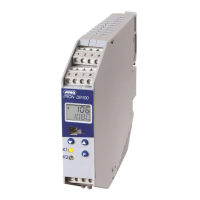
4.3.4 Connection of the PROFIBUS-DP connector
Mounting the
adapter
h Identify option slot with the PROFIBUS-DP interface by means of the
type code (in the case of pre-configured devices)
Assignment of
the 9-pole
D-SUB socket
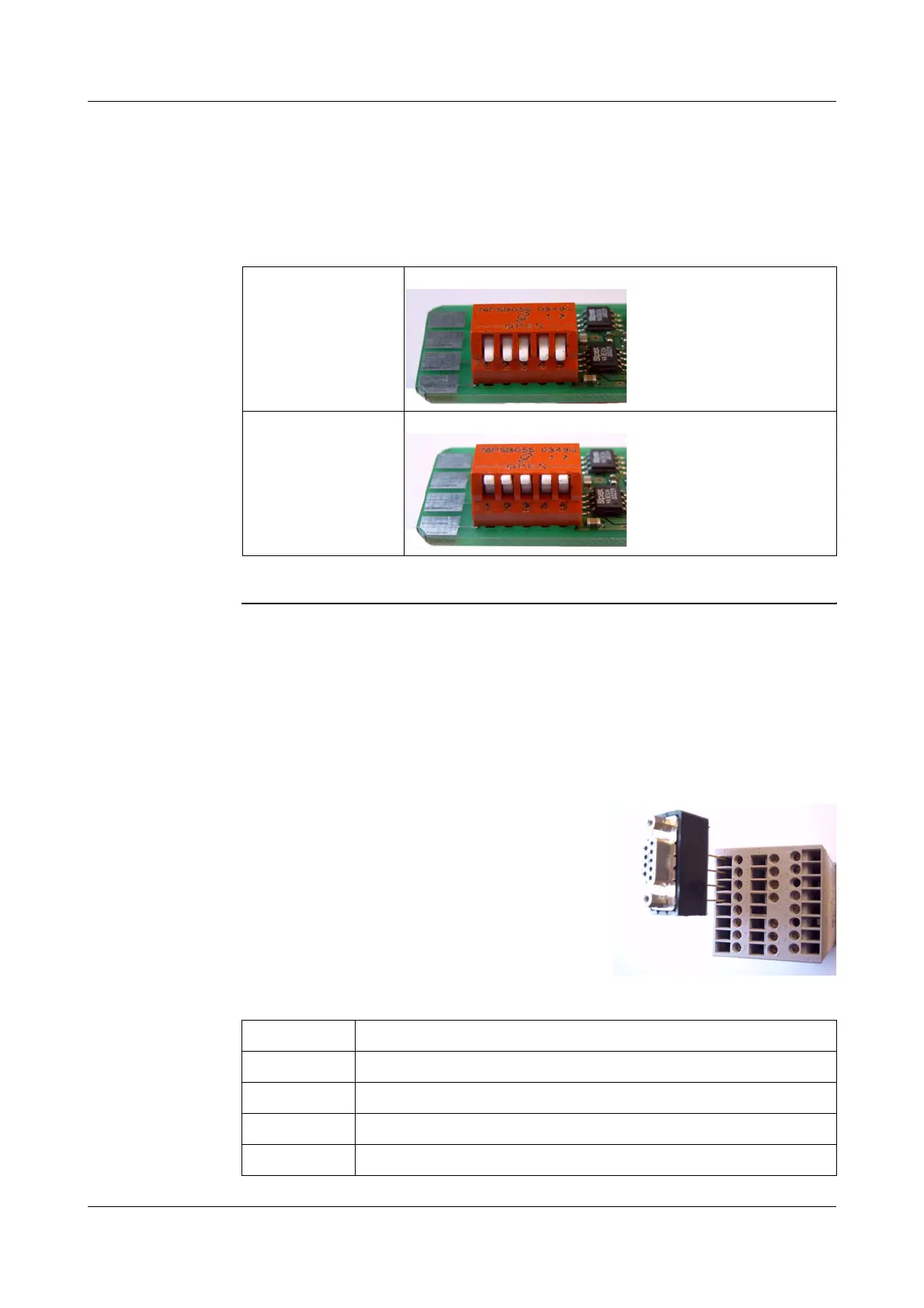
Bus termination
resistor active:
h Push all 5 switches down
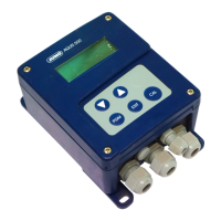
No bus termination
(ex-factory)
h Push all 5 switches up
In this example, the PROFIBUS-DP
interface is in option slot 1
H
To fit the D-SUB adapter, open the housing
of the adapter; otherwise the terminal
screws are hided by the adapter.
Pin: Signal Designation
1: VP Supply voltage positive
2: RxD/TxD-P Receive/Transmit data positive
3: RxD/TxD-N Receive/Transmit data negative
4: DGND Ground