Do you have a question about the KEB COMBILINE Z2 Series and is the answer not in the manual?
Explains hazard symbols and their meanings for safety.
Describes additional symbols used in the documentation.
Information on EC declaration of conformity and CE mark compliance.
Outlines warranty and liability terms for the acquired device.
Guidance on requesting further information or assistance.
States the terms of use for documentation and intellectual property rights.
Defines the qualified electrical personnel for this manual.
Instructions for safe transport, storage, and handling of the filters.
Covers safety precautions and guidelines for device installation.
Details safety measures for electrical wiring and connection.
Safety notes for initiating and operating the device.
Guidelines and warnings regarding repair procedures.
Information on the proper disposal of electronic devices.
Lists product standards relevant to EMC components.
Lists basic standards applicable to environmental conditions.
Lists general standards related to electrical installations and machinery.
Describes the intended installation environment for the output filters.
Warns against operating the product outside specified limits.
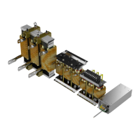
Details the characteristics and benefits of the COMBILINE Z2 output filters.
Outlines climatic and environmental conditions for operation.
Specifies temperature, humidity, and altitude requirements for storage and operation.
Details vibration and shock limit values for different operational phases.
Lists classifications for contamination by gases and solids.
Defines device classification based on pollution degree.
Provides mechanical specifications for motor chokes.
Details connection types, conductor sizes, and tightening torques.
Lists current, inductance, resistance, and power loss for motor chokes.
Provides connection types and tightening torques for capacitor modules.
Lists max current, capacity, and max frequency for capacitor modules.
Details conductor sizes, connections, and max current for cable sets.
Shows compatible combinations of motor chokes, capacitors, and cables.
Provides physical dimensions and weight specifications for components.
Provides dimensions and weights for motor chokes sizes 07 to 12.
Provides dimensions and weights for motor chokes sizes 13 to 19.
Provides dimensions and weights for motor chokes sizes 20 to 22.
Provides dimensions and weights for motor chokes sizes 23 to 30.
Shows dimensions and weight of capacitor modules housed in an enclosure.
Details dimensions and weight of a capacitor module with one power capacitor.
Details dimensions and weight of a capacitor module with two power capacitors.
Details dimensions and weight of a capacitor module with three power capacitors.
Details dimensions and weight of a capacitor module with four power capacitors.
Illustrates the wiring diagram for a motor choke connection.
Shows the wiring diagram for an output filter installation.
Explains the overtemperature protection mechanism for chokes.
Provides electrical data for the NC temperature monitoring contact.
Illustrates the connection terminals for motor chokes size 07 to 12.
Illustrates the connection terminals for motor chokes size 13 to 19.
Illustrates the connection terminals for motor chokes size 20 to 22.
Illustrates the connection terminals for motor chokes size 23 to 30.
Shows an example of connecting capacitor modules using M12 screws.
Illustrates the connection for capacitor modules installed in a housing.
Details the connection of a capacitor module with one power capacitor.
Details the connection of a capacitor module with two power capacitors.
Details the connection of a capacitor module with three power capacitors.
Details the connection of a capacitor module with four power capacitors.
Provides instructions and warnings for transporting motor chokes from size 23.
Information on installing the components within a control cabinet.
Specifies the allowed installation positions for motor chokes.
Specifies the allowed installation positions for capacitor modules.
Details ventilation requirements for motor chokes from size 25.
Shows required clearances for wall mounting components.
Shows required clearances for floor mounting components.
Information on CE marking and compliance with standards.
Details UL certification requirements and conditions of acceptability.
Lists document versions, dates, and descriptions of changes.
Lists contact details for KEB Automation offices globally.
| Category | Water Filtration Systems |
|---|---|
| Brand | KEB |
| Series | Z2 |
| Filtration Technology | Automatic backwash with stainless steel filter element |
| Filter Life | N/A (Self-cleaning) |
| Flow Rate | Varies by model (Consult datasheet) |
| Operating Pressure | 1.5 - 16 bar (21 - 232 psi) |
| Operating Temperature | 5 - 40 °C (41 - 104 °F) |
| Connection Size | Varies by model (Consult datasheet) |
| Dimensions | Varies by model (Consult datasheet) |
| Weight | Varies by model (Consult datasheet) |
| Warranty | Consult manufacturer |