Setup H 6-AFE
FW 1.2 / 1.4
Supply t he AFE only with 24V!
(24V- and charging Unit or H6 PLC
with power su pply conn ecte d to
mains)
Com munic ati on
established?
yes
downl oad Filt er_Downl oa dlist
in AFE unit
Plug X2A, X2B di sconnec t
Error
Fil te r_Dow nl oa dl ist
according to c urent HW
available?
DC Link capacity all am DC Link connected Units add and in
AFE Uni t store.
cu17: … µF
these „alert“ occ urs, beca use t he li st
was created on a different device.
Voltage on the DC link at th is po in t can damage
the de vic e!
See installation instructions electric shock
no
no
yes
the DC Lin k c ap aci ty of the connecte d de vi ce can be
fo und In pa rameter: de35 or the programming guide
set:
dr05, dr06
Basic settings, AC power supply
e.g..: dr05, mains voltage , 40 0V
dr06, line frequency , 50Hz
htt p://w ww.keb.de/de/
service-dow nl oads/
downl oads
set: Is10 := dr53
(Switching frequency AFE Filter)
Only partial load operation is
poss ible!
no
yes
Other lines of communication between PC and
AFE are also possible.
answer message false configuration with „yes“
de15 := 0 ?
set
co08 := 2 Device i s res et to factory settings!
Done
is ru14 ≈cu21
1)
and
st12 = 5?
Requirement:
Hardware circuit electri cally checke d!
Ap pl icati on mee ts the mains c onne ct io n
requi re me nt s!
Che ck i f H6-AFE device
(device type: Node_1_H6_ac ti ve_front_end)
set
co09 := 1
wrong unit!
yes
no
co09 = counts up,
co09 = 0?
Restart drive, c om muni cat ion l ost !
dr49..dr53 according to HW
switching frequency is included
Internet
available?
copy LCL Filter data
dr15, dr17,
dr49-dr53,
dr65-dr66.
is dr02 =2?
no
yes
no
yes
Plug X2A, X2B
disconnect
control word c o00 := 0
Rese t del etes all data
(Also operating hours, etc.)
See programming manual -> LCL filter
Data stored?
control word co00 := 11
ST wi th contro l
wor d?
set I2
set
dr15 an d dr17
is dr02 = 2?
set dr99 := 0
Data stored!
no
yes
1
2
3
4
5
6
7
9
10
11
12
13
14
15
16
17
18
19
20
26
27
28
29
30
31
32
33
34
35
37
yes
no
Presets are included i n fil ter
Downl oa d
save da ta!
no
yes
is line inductance
&netw ork re sis tan ce
known?
set control word
dr99 := 0
set co00 := 3
no
yes
or
set I2 back
38
39
40
42
43
44
45
46
ST OFF
DC li nk dis charged
data saved?
ST
precharging on
control word co00 := 3
Switching frequency AFE> = switching
frequency of AFE filter!
check and set cu21
1)
(DC-vol ta ge), see program mi ng gu id e
DC-Bus PID -> Set point
commissioning at
costumer site?
no
yes
on site co mmiss ioning
47
48
50
49
set
cu99 := 4
accordi ng to the applic ati o n,
optimize the voltage PID
is is10 >= dr53?
no
yes
the input of voltage set point is adapted immediately.
the DC co ntrol volt age is, for example, at 400V (AC) min.
680V (DC).
yes
no
Final commissioning on site
after delivery to the customer!
commissioning at cus to me r
si te?
dr12 := rate d cu rrent of M CB /
de28 * 10 0%
Commissioning under test environment
de28 de29 dr12
is the mains supply > =
rated device power?
Modulation off
Pre ch argi ng o ff
Com mi ssi on ing with
mains i dentif ica tion
no
yes
yes
no
is the AFE-rate d curre nt
de28 <= rate d filter
curr ent ?
set
dr12 := max Filter current / de28
* 10 0%
51
53
52
55
54
Step by step setup H6 AFE
yes
no
is max AFE Filter current <
de29
in dependence on the
cooli ng of the AFE / LCL fi lter
part loa d is poss ible
Is t he ap pa re nt curr ent
limited?
dr12:= max cu rrent ap pl ic at ion /
de28 * 100%
In dependence on the cooling of the
AFE, a partial load opera tion is possible
See sub procedure
identifi cation
set dr12:= de29 / de28 * 100%
Data can be found in t he rel evant
installation manual
AFE/ LCL Filter
maxi mum relat ive
filter current
Rated filter current (IN)
maxi mum fil te r cu rrent (IMAX)
8
no
yes
decision acti on
st art / end
comment
questi on
is sue
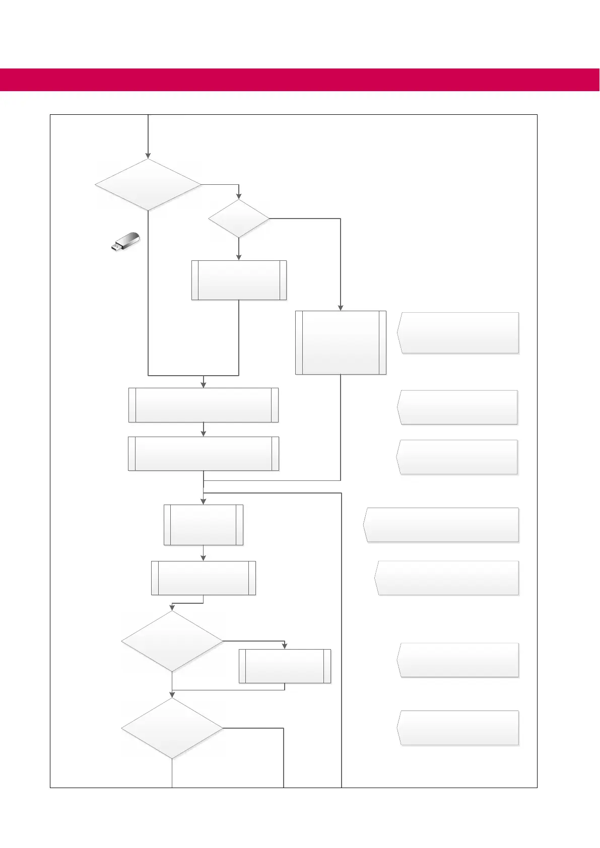
Explanation:
ex te rnal HW
Note:
These commissioning instructions should be read and executed from left to right from top to
bottom. The direction of the arrow gives the sequence of the individual steps. The order is
important! Some settings are based on other settings, which need to be set in advance.
1) With software V1.4 the setpoint of the control voltage "Target Uic" is indicated in parameter
IDText cu18 instead of parameter cu21.
56
column number
21
22
23
24
25
36
41
Version: 1.1 / 05.05.2020
COMBIVIS with USB Adaptor
connected t o AFE
Ethernet Adaptor
or
Impor tant !
charging maximum load / relative current value.
yes
no
set is10 := AIC rated switching
fr equency
Important otherwise overcurrent fault!
AFE ra ted s wi tc hi ng freq ue nc y
(See installation manual for technical
data)
Connector X2A, X2B
Plug in
Set HW ST
fi nal f unct io n te st
set point vol tage r eac he d and A FE
modul ate s?
56
74
START-UP
 Loading...


