Keithley Instruments, Inc.
Cleveland, Ohio 44139
DRN.
CKD.
APP.
DATE
DATE
DATE
PART NUMBER
LTR REVISIONS APP. DATE
FORM 28777A-SBG
BRUNING 40-21 62198-SBG
PURCHASED ITEM
SPECIFICATIONS
HW 8/01/02
Revision A
Page 2 of 3
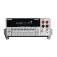
2701 Ethernet Multimeter/Data Acquisition System
DC Notes
1. 20% overrange except on 1000V and 3A.
2. Add the following to “ppm of range” uncertainty; 100mV 15ppm; 1V and 100V 2ppm; 100Ω 30ppm;
1k→1MΩ 2ppm, 20mA and 1A 10ppm, 100mA 40ppm.
3. ±2% (measured with 10MΩ input resistance DMM, >10GΩ DMM on 10MΩ and 100MΩ ranges).
4. Relative to calibration accuracy.
5. For signal levels >500V, add 0.02ppm/V uncertainty for portion exceeding 500V.
6. Specifications are for 4-wire Ω, 100Ω with offset compensation on, with 77xx plug-in modules, with
Lsync on and with offset compensation on, OPEN CKT. VOLTAGE is 12.8V. For 2-wire Ω add 1.0Ω to
“ppm of range” uncertainty.
7. Must have 10% matching of lead resistance in Input HI and LO.
8. Add the following to “ppm of reading” uncertainty when using plug in modules:
10 kΩ 100 kΩ 1 MΩ 10 MΩ 100 MΩ
All Modules: 220 ppm 2200 ppm
7701, 7703, 7707, 7709 Modules: 10 ppm 100 ppm 1000 ppm 1% 10%
7706, 7708 Modules: 5 ppm 50 ppm 500 ppm 5000 ppm 5%
9. Add 1.0V when used with plug in modules.
10. For RATIO, DCV only. For AVERAGE, DCV and Thermocouples only. Available with plug in modules
only.
11. Add 6µV to “of range” uncertainty when using Models 7701, 7703, and 7707, and 3µV for Models 7706 and
7709.
12. Auto zero off.
13. For LSYNC On, line frequency ±0.1 %. For LSYNC Off, use 60dB for ≥ 1PLC.
14. For 1kΩ unbalance in LO lead.
15. Speeds are for 60Hz (50Hz) operation using factory defaults operating conditions (*RST). Autorange
off, Display off, Limits off, Trigger delay = 0.
16. Speeds include measurements and data transfer out the ethernet (reading element only). (100BaseT
Ethernet, 3 meter RJ-45 crossover cable, PIII-800, Windows version 98 SE, VB version 6.0, direct
Winsocket interface).
17. Sample count = 1000 (into memory buffer), auto zero off.
18. Auto zero off, NPLC = 0.002.
19.
Additional Uncertainty Plug-In Modules
Front Terminals 7709
7701, 7703, 7707
7700, 7708 ,7710 7706
Simulated Simulated Simulated Using Using
Type Range Ref. Junction Ref. Junction Ref. Junction CJC CJC
J –200 to 0°C 0.1 0.1 0.3 0.8 1.6
K –200 to 0°C 0.2 0.2 0.4 0.8 1.6
N –200 to 0°C 0.3 0.3 0.6 0.8 1.6
T –200 to 0°C 0.2 0.1 0.4 0.8 1.6
E –200 to 0°C – 0.1 0.3 0.8 1.6
R 0 to +400°C 0.4 0.6 1.2 0.5 1.0
S 0 to +400°C 0.4 0.6 1.2 0.5 1.0
B +350 to +1100°C 0.8 0.3 1.7 0.5 1.0
20. For lead resistance >0Ω, add the following uncertainty/Ω for measurement temperatures of:
70°–100°C 100°–150°C
2.2 kΩ (44004) 0.22°C 1.11°C
5.0 kΩ (44007) 0.10°C 0.46°C
10 kΩ (44006) 0.04°C 0.19°C
21. Front panel resolution is limited to 0.1Ω.
AC SPECIFICATIONS
1
Accuracy: ±(% of reading + % of range), 23°C ± 5°C
Calibration 3 Hz– 10 Hz– 20 kHz– 50 kHz– 100 kHz–
Function Range Resolution Cycle 10 Hz 20 kHz
8
50 kHz 100 kHz 300 kHz
Voltage
2
100.0000 mV 0.1 µV 90 Days 0.35 + 0.03 0.05 + 0.03 0.11 + 0.05 0.6 + 0.08 4.0 + 0.5
1.000000 V 1.0 µV (all ranges)
10.00000 V 10 µV 1 Year 0.35 + 0.03 0.06 + 0.03 0.12 + 0.05 0.6 + 0.08 4.0 + 0.5
100.0000 V 100 µV (all ranges)
750.000 V 1.0 mV
(Temp. Coeff.)/°C
3
0.035 + .003 0.005 + .003 0.006 + .005 0.01 + .006 0.03 + .01
3 Hz–10 Hz 10 Hz–3 kHz 3 kHz–5 kHz
Current
2
1.000000 A 1.0 µA 90 Day/1 Yr. 0.3 + 0.04 0.10 + 0.04 0.14 + 0.04
3.00000 A 10 µA 0.35 + 0.06 0.15 + 0.06 0.18 + 0.06
(Temp. Coeff.)/°C
3
0.035 + 0.006 0.015 + 0.006
Accuracy ± (ppm of reading + offset ppm)
(3 Hz–500 kHz) (333 ms–2 µs)
Frequency
4
100 mV 0.333 ppm 90 Day/ 1 Yr. 100 ppm + 0.333 ppm (SLOW, 1s gate)
and Period to 3.33 ppm 100 ppm + 3.33 ppm (MED, 100ms gate)
750 V 33.3 ppm 100 ppm + 33.3 ppm (FAST, 10ms gate)
DC SPEED vs. NOISE REJECTION
RMS Noise
Rate Filter Readings/s
12
Digits 10V Range NMRR CMRR
14
10 50 0.1 (0.08) 6.5 < 2.5 µV 110 dB
13
140 dB
1 Off 15 (12) 6.5 < 6 µV 90 dB
13
140 dB
0.1 Off 500 (400) 5.5 < 40 µV — 80 dB
0.006 Off 3000 (3000) 4.5 < 300 µV — 80 dB
0.002 Off 3500 (3500) 3.5 < 1mV — 60dB
DC MEASUREMENT CHARACTERISTICS
DC Volts
A-D LINEARITY: 2.0 ppm of reading + 1.0 ppm of range.
INPUT IMPEDANCE:
100mV–10V Ranges: Selectable >10GΩ // with <400pF or 10MΩ ±1%.
100V, 1000V Ranges: 10MΩ ±1%.
EARTH ISOLATION: 500V peak, >10GΩ and <300pF any terminal to
chassis.
INPUT BIAS CURRENT: <75pA at 23°C.
COMMON MODE CURRENT: <500nApp at 50Hz or 60Hz.
AUTOZERO ERROR: Add ±(2ppm of range error + 5µV) for < 10 minutes
and ±1°C.
INPUT PROTECTION: 1000V, all ranges. 300V with plug in modules.
Resistance
MAX 4WΩ LEAD RESISTANCE: 10% of range per lead for 100Ω, and 1kΩ
ranges; 1kΩ per lead for all other ranges.
OFFSET COMPENSATION: Selectable on 4WΩ, 100Ω, 1kΩ, and 10kΩ
ranges.
CONTINUITY THRESHOLD: Adjustable 1 to 1000 Ω
INPUT PROTECTION: 1000V, all Source Inputs, 350V Sense Inputs. 300V
with plug-in modules.
DC Current
SHUNT RESISTORS: 100mA–3A, 0.1Ω. 20mA, 5Ω.
INPUT PROTECTION: 3A, 250V fuse.
Thermocouples
CONVERSION: ITS-90.
REFERENCE JUNCTION: Internal, External, or Simulated (Fixed).
OPEN CIRCUIT CHECK: Selectable per channel. Open >11.4k ± 200Ω.
SPEC-2701

 Loading...