4-8 Troubleshooting Model 2701 Service Manual
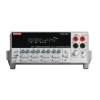
Display
DS401 is the display module, which can display up to 12 alpha-numeric characters and
includes the various annunciators.
The display uses a common multiplexing scheme with each character refreshed in sequence.
U402 and U403 are the drivers for the display characters and annunciators. Note that data for
the drivers are serially transmitted from the microcontroller (MOSI and PC1).
Filament voltage for the display is derived from the power supply transformer (F1 and F2).
The display drivers require +37VDC and +5VDC, which are supplied by U144 (+5VD) and
U101 (+37V).
Key matrix
The front panel keys (S401-S430) are organized into a row-column matrix to minimize the
number of microcontroller peripheral lines required to read the keyboard. A key is read by
strobing the columns and reading all rows for each strobed column. Key-down data is
interpreted by the display microcontroller and sent back to the main microprocessor using
proprietary encoding schemes.
Digital circuitry
Refer to Figure 4-2 for the following discussion on digital circuitry.
Main microprocessor
U1 is an MCF5407 microprocessor that oversees all operating aspects of the instrument
except the Ethernet interface (see below). The MPU has a 32-bit data bus and provides a 24-bit
address bus. It also has integrated peripheral support such as 16-bit I/O, an integral DRAM
controller with SDRAM support, and UARTs, one of which is used for the RS-232 interface.
The MPU clock frequency of 50MHz is controlled by crystal Y1. MPU RESET is per-
formed momentarily on power-up.
Memory circuits
U6 is the flash memory that stores the firmware code for instrument operation and SDRAM
U3 provides temporary storage for the MPU. A battery watchdog control automatically senses
when the +5VD supply is being powered down and then switches to the lithium ion battery for
power. Battery charge is maintained by U4 and associate components.
Real time clock
U7 is the real time clock. The clock runs from main power and switches to two 0.33F capac-
itors (C43, C44) on power down and can hold the time for up to six months.

 Loading...