Model 2701 Service Manual Performance Verification 1-15
6. Source the nominal full-scale resistance values for the 100Ω-10MΩ ranges summarized
in Table 1-6 and verify that the readings are within calculated limits.
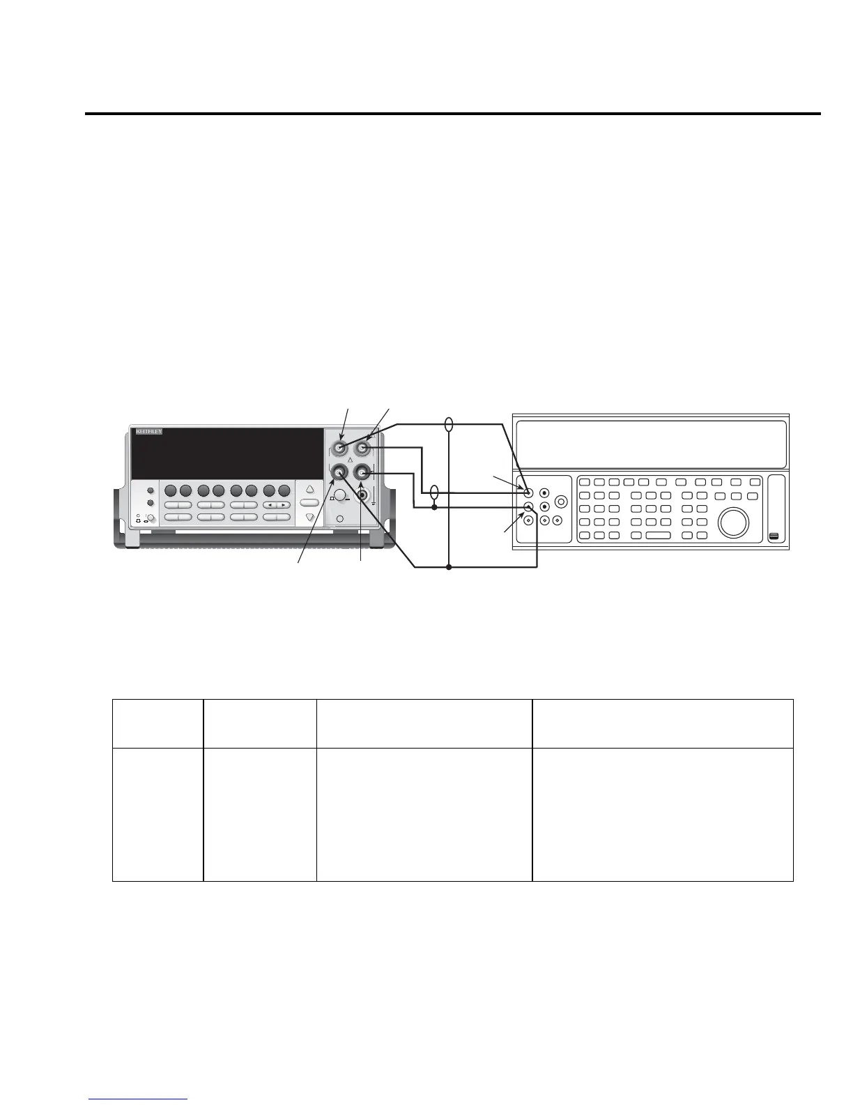
7. Connect the Model 2701 INPUT and SENSE jacks to the calibrator as shown in
Figure 1-6.
8. Disable external sense on the calibrator.
9. Set the Model 2701 for the 100MΩ range.
10. Source a nominal 100MΩ resistance value and verify that the reading is within calcu-
lated limits for the 100MΩ range.
Figure 1-6
Connections for Model 2701 resistance verification (100MΩ range)
Table 1-6
Limits for resistance verification
Ω Range
Nominal
resistance
Nominal reading limits
(1 year, 18°C to 28°C) Recalculated limits**
100Ω∗
1kΩ
10kΩ
100kΩ
1MΩ
10MΩ
100MΩ
100Ω
1kΩ
10kΩ
100kΩ
1MΩ
10MΩ
100MΩ
99.9880 to 100.0120Ω
0.999894 to 1.000106kΩ
9.99894 to 10.00106kΩ
99.9890 to 100.0110kΩ
0.999890 to 1.000110MΩ
9.99590 to 10.00410MΩ
99.7970 to 100.2030MΩ
__________ to __________ Ω
__________ to __________ kΩ
__________ to __________ kΩ
__________ to __________ kΩ
__________ to __________ MΩ
__________ to __________ MΩ
__________ to __________ MΩ
* Enable O COMP (offset-compensated ohms) when testing 100Ω range.
** Calculate limits based on actual calibration resistance values and Model 2701 one-year resistance accuracy specifications. See
Verification limits.
!
Model 2701 Ethernet Multimeter / Data Acquisition System
RANGE
F
500V
PEAK
FRONT/REAR
3A 250V
AMPS
HI
INPUT
LO
SENSE
Ω 4 WIRE
INPUTS
350V
PEAK
1000V
PEAK
AUTO
SHIFT
LOCAL
POWER
RANGE
R
EXIT ENTER
DIGITS RATE
RELFILTER
TRIG
EX TRIG
STORE
RECALL
OPEN
DCV
DCI
MATH
OUTPUT
RATIO
ACV
ACI
Ω2 Ω4
FREQ
TEMP
CH AVG
CONT
PERIOD SENSOR
LIMITS ON/OFFDELAY
HOLD
SAVE SETUP
CONFIG HALT
TYPE
LSYNC
TEST
MONITOR
STEP SCAN
OCOMP
CH-OFF CARD
CLOSE
Integra Series
RS-232ETHERNET
Resistance Calibrator
Note: Use shielded, low-thermal cables to
minimize noise. Disable calibrator
external sense.
Model 2701
OUTPUT
HI
OUTPUT
LO
INPUT
HI
SENSE
HI
SENSE
LO
INPUT
HI
CAT I

 Loading...


