6482-901-01 Rev. A / August 2012 Return to Section Topics 8-7
Model 6482 Dual-Channel Picoammeter / Voltage Source Reference Manual Section 8: Triggering
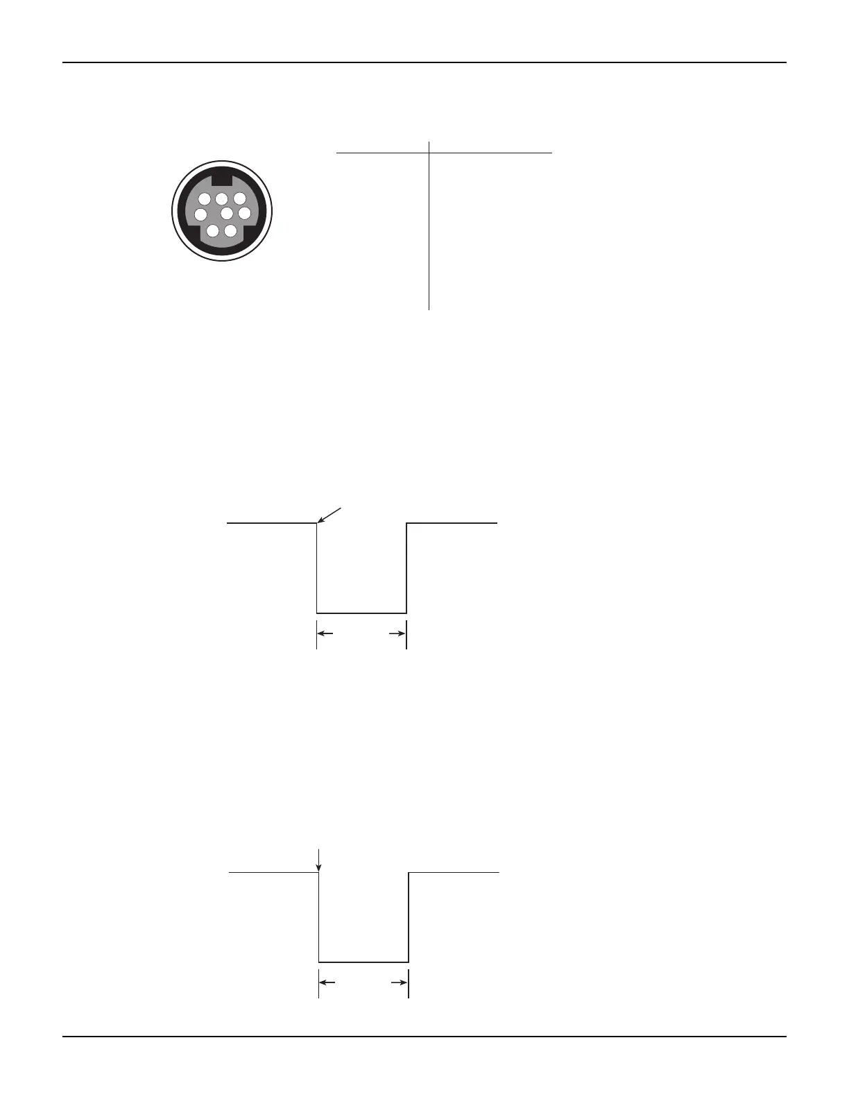
Figure 8-2
Rear panel trigger link pinout
Input trigger requirements
An input trigger is used to satisfy event detection for a trigger model layer that is configured for the
trigger link event. See “Front-panel operation of the trigger model.” The input requires a falling-
edge, TTL-compatible pulse with the specifications shown in Figure 8-3.
Figure 8-3
Trigger link input pulse specifications
Output trigger specifications
The Model 6482 can be programmed to output a trigger after various trigger model actions. See
“Front-panel operation of the trigger model.” The output trigger provides a TTL-compatible output
pulse that can be used to trigger other instruments. The specifications for this trigger pulse are
shown in Figure 8-4. A trigger link line can source 1 mA and sink up to 50 mA.
Figure 8-4
Trigger link output pulse specifications
TRIGGER LINK
Pin number
Description
6
34
7
5
2
1
8
1
2
3
4
5
6
7
8
Trigger Link 1
Trigger Link 2
Trigger Link 3
Trigger Link 4
Trigger Link 5
Trigger Link 6
Ground
Ground
TTL high
(2 V-5 V)
TTL low
(-0.8 V)
10 μs
minumum
Triggers on
leading edge
Meter complete
TTL High
(3.4 V Typical)
TTL Low
(0.25 V Typical)
10 μs
minumum