6482-901-01 Rev. A / August 2012 Return to Section Topics 11-3
Model 6482 Dual-Channel Picoammeter / Voltage Source Reference Manual Section 11: Output Enable and Output Configuration
For front-panel operation of the trigger model, see “Event detection” on page 8-3; for remote
operation, see “Event detection” on page 8-15.
+5 V DC
The OUTPUT ENABLE connector provides a +5 V DC output on pin 7 that can be used to drive
external logic circuitry. Maximum current output for this line is 300 mA. This line is protected by a
self-resetting fuse (one hour recovery time).
Output enable (/OE)
NOTE The forward slash (as shown /OE) designates that the pin is active low (in other words,
when connected to ground).
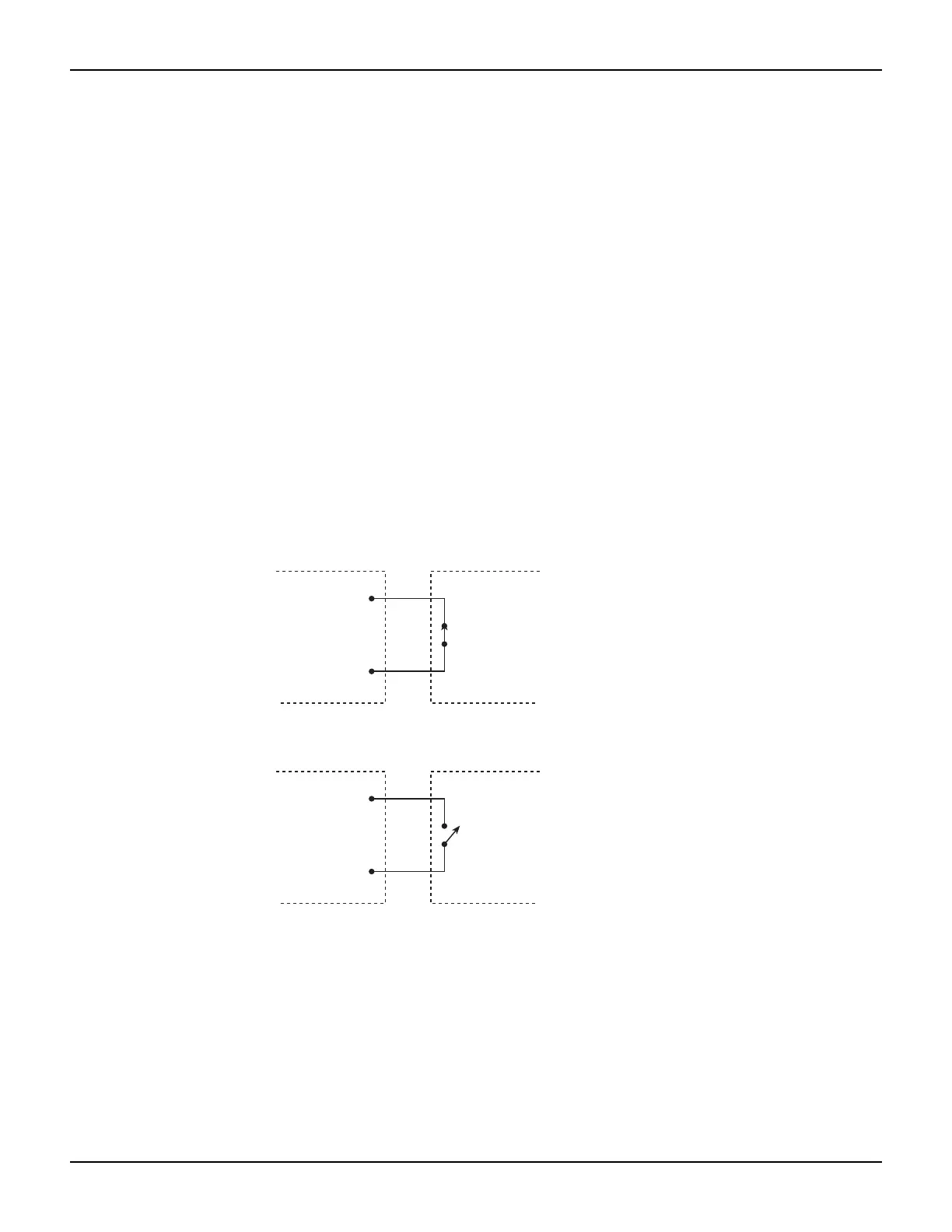
When output enable is activated (see “Front-panel output configuration,” page Section 11-4), the
output of the Model 6482 cannot be turned on unless the output enable line is pulled low through a
switch to ground as shown in Figure 11-2A. If the lid of the test fixture opens (Figure 11-2B), the
switch opens, and the output enable line goes high turning the output of the Model 6482 OFF (high
impedance). The output can only be turned back on by first closing the lid of the test fixture and
then pressing the OUTPUT ON/OFF key.
Figure 11-2
Using test fixture output
GND
(Pin 5 or 9)
OUTPUT
ENABLE
OUTPUT
ENABLE
Model 6482 Test fixture
GND
(Pin 5 or 9)
Model 6482 Test fixture
A. Model 6482 output can be turned on.
B. Model 6482 ouput turns off.
Output
enable
(Pin 8)
Output
enable
(Pin 8)
Switch open
(lid open)
Switch closed
(lid closed)