6482-901-01 Rev. A / August 2012 Return to Section Topics 12-15
Model 6482 Dual-Channel Picoammeter / Voltage Source Reference Manual Section 12: Remote Operations
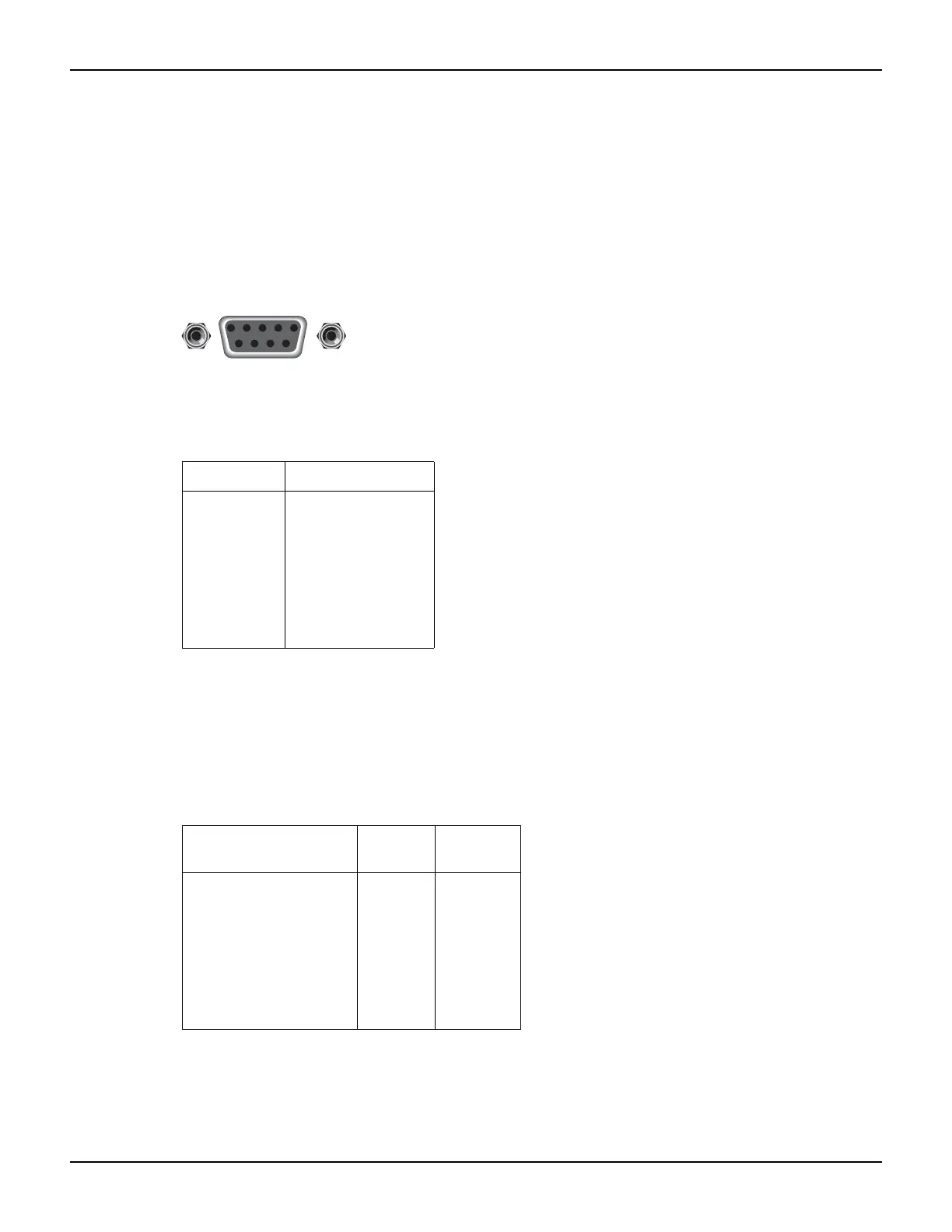
serial port uses the transmit (TXD), receive (RXD), and signal ground (GND) lines of the RS-232
standard. Figure 12-4 shows the rear panel connector for the RS-232 interface, and Table 12-2
shows the pinout for the connector.
If your computer uses a DB-25 connector for the RS-232 interface, you will need a cable or
adapter with a DB-25 connector on one end, and a DB-9 connector on the other. Make sure the
cable is wired straight through (not null modem).
Figure 12-4
RS-232 interface connector
Table 12-3 provides pinout identification for the 9-pin (DB-9) or 25-pin (DB-25) serial port
connector on the computer.
Error messages
See Appendix A for RS-232 error messages.
Table 12-2
RS-232 connector pinout
Pin number Description
1
2
3
4
5
6
7
8
9
Not used
TXD, transmit data
RXD, receive data
Not used
GND, signal ground
Not used
RTS, ready to send
CTS, clear to send
Not used
Note: CTS and RTS are tied together.
Pins 1, 4, and 6 are tied together.
Table 12-3
Computer serial port pinout
Signal
DB-9 pin
number
DB-25 pin
number
DCD, data carrier detect
RXD, receive data
TXD, transmit data
DTR, data terminal ready
GND, signal ground
DSR, data set ready
RTS, request to send
CTS, clear to send
RI, ring indicator
1
2
3
4
5
6
7
8
9
8
3
2
20
7
6
4
5
22
Rear panel connector
9876
54321
RS-232