6482-901-01 Rev. A / August 2012 Return to Section Topics 2-3
Model 6482 Dual-Channel Picoammeter / Voltage Source Reference Manual Section 2: Connections
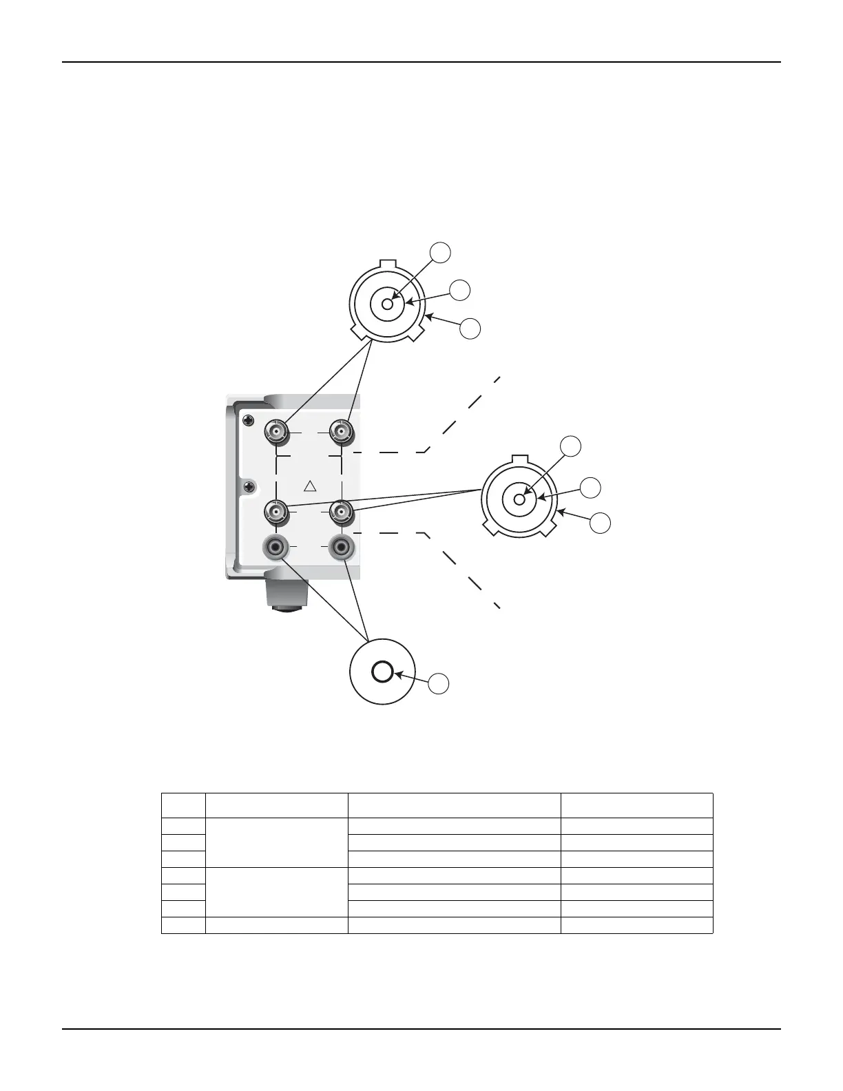
Connector terminals
The electrical configuration of the input, analog output, and voltage source connectors are shown
in Figure 2-2 and Table 2-1.
Figure 2-2
Connector terminals
Table 2-1
Connector terminal legend
Item Connector Description Terminal
1
Input
Input HI Inner conductor
2 Input LO (analog common) Inner shield
3 Chassis ground Outer shield
4
Analog output
Analog output HI Inner conductor
5 Analog output LO (analog common) Inner shield
6 Chassis ground Outer shield
7 Voltage source output Voltage source (output) Safety banana jack
CAT
I
INPUT
RATINGS MAX.
30 V @ 20mA
CHANNEL 1
CHANNEL 2
RATINGS MAX.
COMMON
MODE
200V
!
ANALOG
OUT
RATINGS MAX.
30 V @ 20mA
VOLTAGE
SOURCE
OUT
30 V @ 20mA
1
2
3
4
5
6
7
Input
(triaxial)
Voltage source output
(banana jack)
Analog output
(triaxial)