6482-901-01 Rev. A / August 2012 Return to Section Topics 9-5
Model 6482 Dual-Channel Picoammeter / Voltage Source Reference Manual Section 9: Measurement Concepts
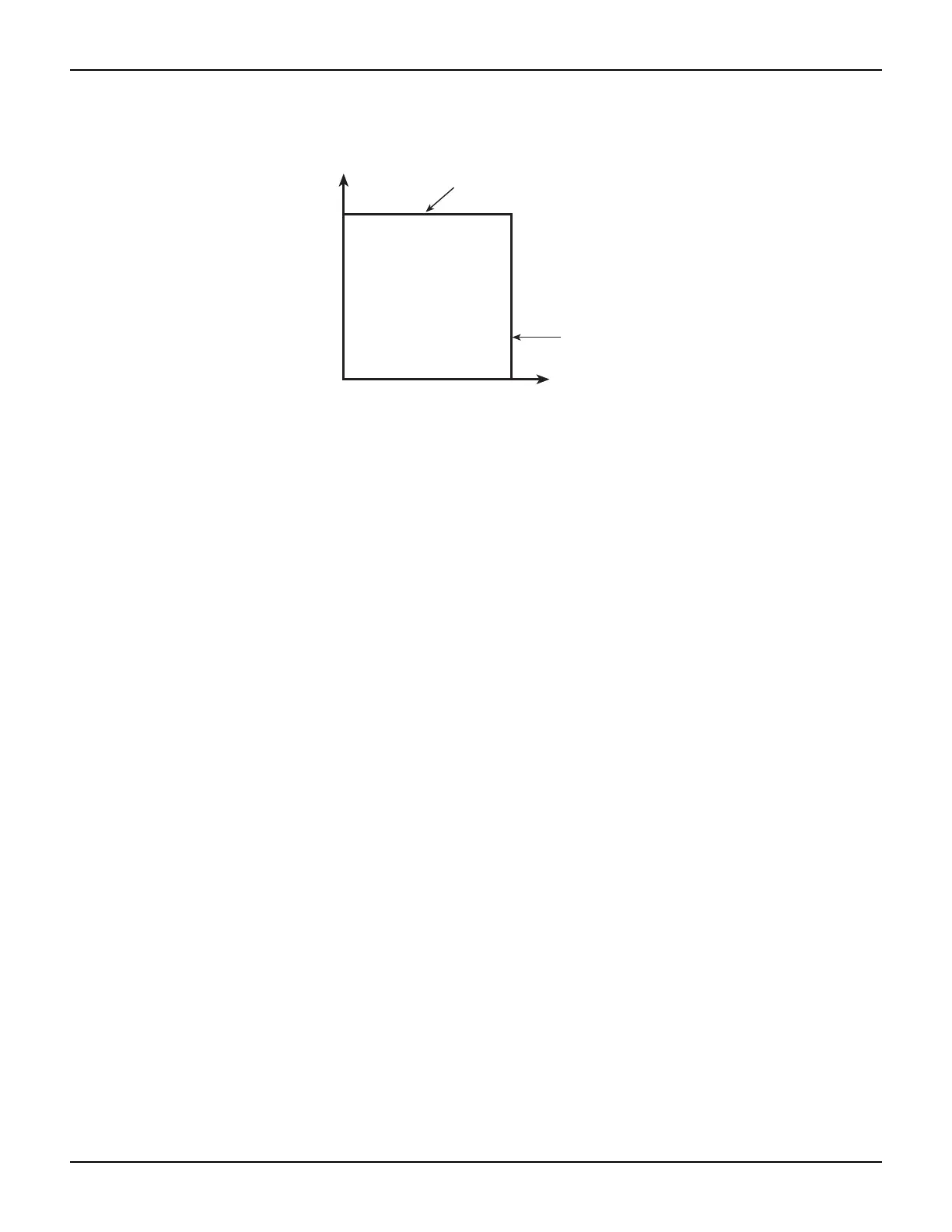
Figure 9-4
Bias source limit lines
Loading effects
The specific location within the boundaries each bias source operates depends on the resistance
of the load (also called the device under test or DUT) that is connected to the output. Figure 9-5
shows operation examples for resistive loads that are 1 kΩ and 400 Ω, respectively. For these
examples, one bias source (of the Model 6482) is programmed to source 10 V with a fixed current
limit of 20 mA.
In Figure 9-5A, the Model 6482 is sourcing 10 V into the 1 kΩ load, and subsequently sources 10
mA. As shown, the load line for 1 kΩ intersects the 10 V voltage source line at 10 mA.
Figure 9-5B shows what happens if the resistance of the load is decreased to 400 Ω . The DUT
load line for 400 Ω intersects the 20 mA current compliance limit line, placing the Model 6482 in
compliance. In compliance, the Model 6482 will not be able to source its programmed voltage (10
V). For the 400 Ω DUT, the instrument will output only 8 V (at the fixed 20 mA limit).
Notice that as resistance increases, the slope of the DUT load line decreases. As resistance
approaches infinity (open output), the Model 6482 will source virtually 10 V at 0 mA. Conversely,
as resistance decreases, the slope of the DUT load line increases. At zero resistance (shorted
output), the Model 6482 will source virtually 0 V at 20 mA.
Regardless of the load, current will never exceed the fixed compliance of 20 mA.
–30 V
(maximum)
Current compliance
limit line
Output
current
Output voltage
Voltage source
limit line
–20 mA
(maximum)