2-8 Return to Section Topics 6482-901-01 Rev. A / August 2012
Section 2: Connections Model 6482 Dual-Channel Picoammeter / Voltage Source Reference Manual
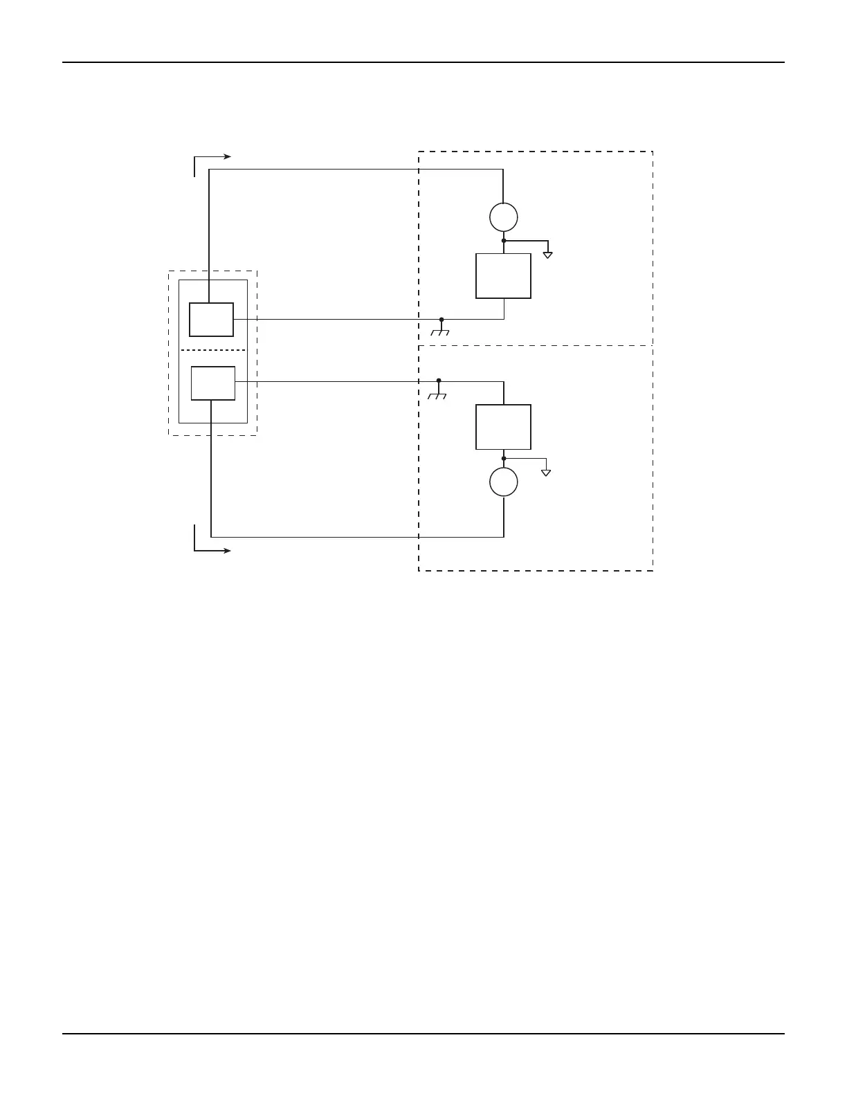
Figure 2-6
Ground connect mode equivalent circuit
Analog output connections
WARNING Analog output low can float up to ±30 V. Use care to avoid a shock hazard
when using the analog outputs.
For connector location, refer to “Input and output connectors” on page 2-2; for terminal
information, refer to “Connector terminals” on page 2-3.
Nonisolated connections
Figure 2-7 shows typical nonisolated analog output connections. Note that analog output HI
(center conductor) is connected to INPUT HI of the measurement instrument and analog output
LO (inner shield) is connected to INPUT LO.
Model 6482
A
A
INPUT HI
INPUT HI
Channel 1
Channel 2
Channel 1
analog
common
Channel 2
analog
common
Current flow (I)
Current flow (I)
Chassis ground
Chassis ground
INPUT
outer shield
INPUT
outer shield
DUT 1
DUT 2
V-source
V-source