17-18 Return to Section Topics 6482-901-01 Rev. A / August 2012
Section 17: Calibration Model 6482 Dual-Channel Picoammeter / Voltage Source Reference Manual
3. Use the EDIT and keys to select the letter or number, and use the and arrow keys to
choose the position. Press EDIT
for letters; for numbers. Enter the present password on
the display. Front-panel default: 006482.
4. Press the ENTER key to complete the process.
5. Press the EXIT key to return to normal display.
Step 2. Input offset voltage calibration adjustment
1. Install a triaxial shielding cap on both INPUT connectors.
2. Select OFFSET from the CAL EXECUTION menu, and then press the ENTER key. The
instrument will display:
CURRENT OFFSET CAL
Input 0 A then press ENTER
3. Press the ENTER key to complete input voltage calibration.
NOTE This step calibrates offset voltage for both channels.
Step 3. Channel 1 voltage source calibration adjustment
Follow the steps below to calibrate both channel 1 bias voltage ranges. Table 17-8 summarizes
calibration ranges and voltages.
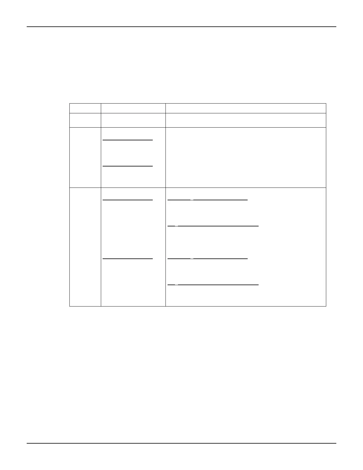
Table 17-7
Front-panel calibration summary
Function
1
Calibration step
2
Test connections
OFFSET INPUT offset voltage
calibration
Channel 1 and channel 2 INPUT connectors left open (capped).
V-CAL
CHAN-1
CHAN-2
Voltage bias calibration
Channel 1 calibration
Positive full-scale output
Zero output
Negative full-scale output
Channel 2 calibration
Positive full-scale output
Zero output
Negative full-scale output
DMM to channel 1 OUTPUT and INPUT connectors (Figure 17-7)
DMM to channel 1 OUTPUT and INPUT connectors (Figure 17-7)
DMM to channel 1 OUTPUT and INPUT connectors (Figure 17-7)
DMM to channel 2 OUTPUT and INPUT connectors (Figure 17-8)
DMM to channel 2 OUTPUT and INPUT connectors (Figure 17-8)
DMM to channel 2 OUTPUT and INPUT connectors (Figure 17-8)
I-CAL
CHAN-1
CHAN-2
Current calibration
Channel 1 calibration
Positive full-scale input
Zero input
Negative full-scale input
Positive full-scale input
Zero input
Negative full-scale input
Channel 2 calibration
Positive full-scale input
Zero input
Negative full-scale input
Positive full-scale input
Zero input
Negative full-scale input
2 nA to 2
μA ranges (Model 6430)
Source to channel 1 INPUT connector (Figure 17-9)
Source to channel 1 INPUT connector (Figure 17-9)
Source to channel 1 INPUT connector (Figure 17-9)
20
μA to 20 mA ranges (Model 5700A)
Source to channel 1 INPUT connector (Figure 17-10)
Source to channel 1 INPUT connector (Figure 17-10)
Source to channel 1 INPUT connector (Figure 17-10)
2 nA to 2
μA ranges (Model 6430)
Source to channel 2 INPUT connector (Figure 17-11)
Source to channel 2 INPUT connector (Figure 17-11)
Source to channel 2 INPUT connector (Figure 17-11)
20
μA to 20 mA ranges (Model 5700A)
Source to channel 2 INPUT connector (Figure 17-12)
Source to channel 2 INPUT connector (Figure 17-12)
Source to channel 2 INPUT connector (Figure 17-12)
1
CAL EXECUTION menu selections.
2
Steps repeated separately for each range.