Getting Started
24
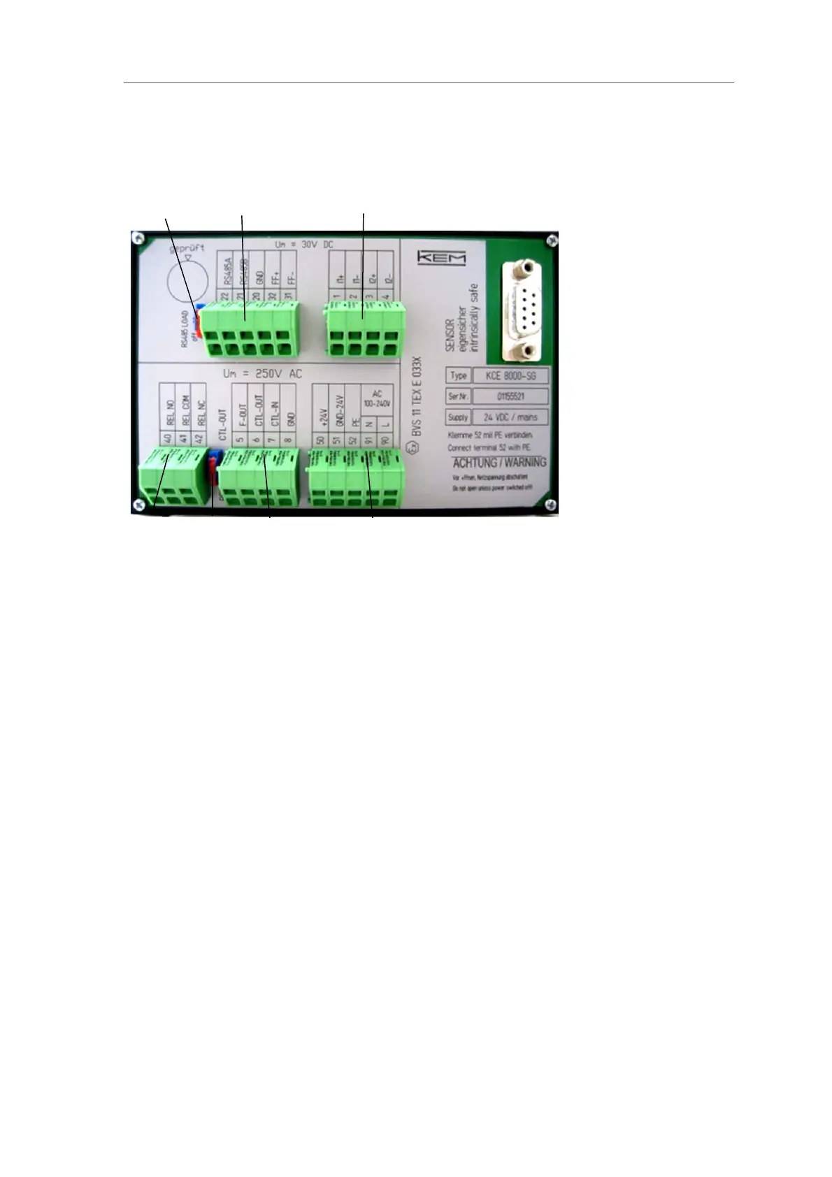
2.3.4 Panel mount version TCE80xx-L-*-Ex
Fig. 11: Electrical terminals TCE80xx-L-*-Ex
1 = Sliding switch for activating the 120 terminal resistance for RS-485
2 = Terminal blocks for interface (U
M
= 30V DC)
3= Terminal blocks for analog I/O signals (U
M
= 30V DC)
4 = Terminal block for power supply (U
M
= 250V DC)
5 = Terminal block for digital I/O signals (U
M
= 250V DC)
6 = Sliding switch for activating the relay output (Option)
7 = Terminal block for relay (U
M
= 250V DC)
2
3
1
5
7
6
4
 Loading...