Installation
38
The control input requires a high voltage of minimum 6.5V and a minimum input current of 0.1mA.
The ground terminals 8 and 51 are internally connected together.
Ground and protective ground are internally connected via a 1k resistor. The resistor will thermally withstand a
potential difference of up to 30V between PE and GND but for proper operation this difference should be limited to
5V.
3.2.6 Connecting the analog outputs
The TCE8000 provides 2 independent passive 4-20mA current loops CURRENT 1 and CURRENT 2.
The current loops are isolated from each other and from the power supply.
For operation an external supply of 8 to 30V (nominal 24V) is required.
The minimum voltage between terminal 1 and 2 or 3 and 4 respectively is 8V.
The minimum load resistance is 0, the maximum is determined by the supply voltage.
At a given supply voltage the maximum load resistance can be calculated as:
R
load
(max) = (V
supply
– 8V) / 22mA
For 24V minus 10% supply this gives a maximum value of 620.
With a given load resistance, the minimum supply voltage can be calculated as:
V
supply
(min) = 8V + R
load
* 22mA
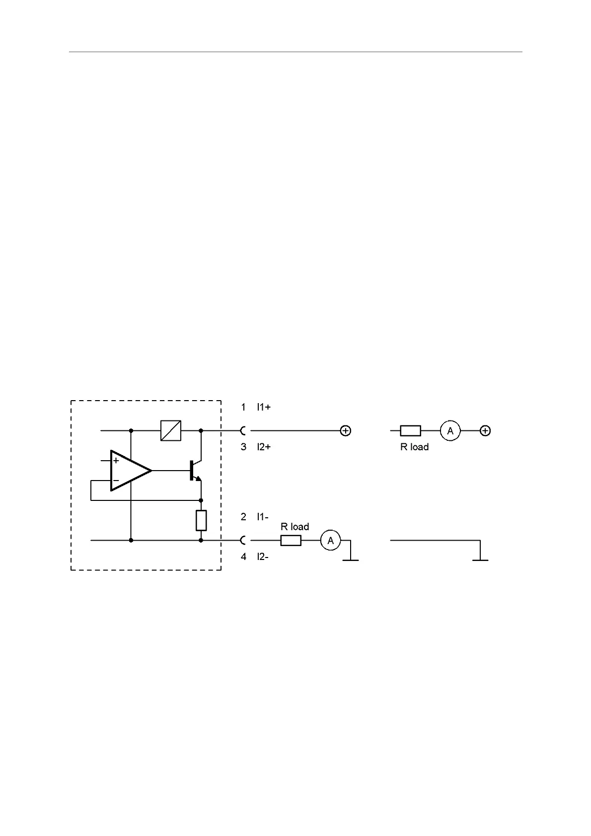
Fig. 19: Wiring diagram for 4-20mA current loop
Terminal Description
1 Positive terminal of the passive 4-20mA loop 1
2 Negative terminal of the passive 4-20mA loop 1
3 Positive terminal of the passive 4-20mA loop 2
4 Negative terminal of the passive 4-20mA loop 2
As the terminals are floating, the load resistor and the current meter can be placed in the positive or in the
negative supply rail (see Fig. 19, right or left circuit).
Connect the shield of the cables to protective ground (terminal 52).
TCE8000
 Loading...