Installation
37
3.2.5 Connecting the control inputs and outputs
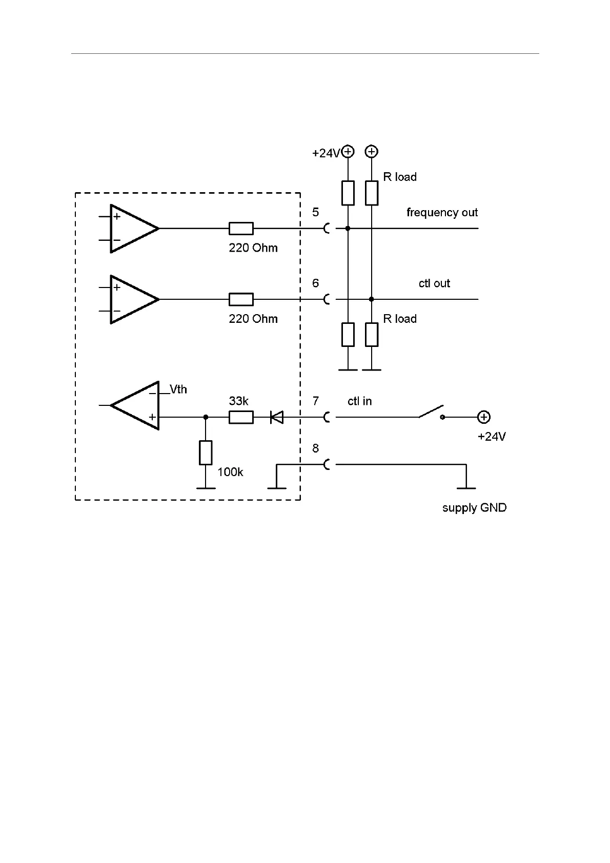
Fig. 18: Wiring diagram for digital I/O connections
Terminal Description
5 Frequency output, active, referred to pin 8
6 Status output, active, referred to pin 8
7 Control input, active high, referred to pin 8
8 Ground potential for digital I/O- pins.
The frequency and control outputs are active push-pull outputs with an output resistance of 220. They can be
loaded to the positive supply or to ground. For a high output swing the load resistors R
load
should not be lower
than 1k.
In case of a load resistor to ground the output voltages are:
V
high = Vsupply * R
load
/ (220 + R
load
)
V
low < 1V
In case of a load resistor to the positive supply the output voltages are:
V
high > Vsupply – 1V
V
low = Vsupply - Vsupply * R
load
/ (220 + R
load
)
TCE8000
 Loading...