X8 MIG WELDER 2.5 Operation
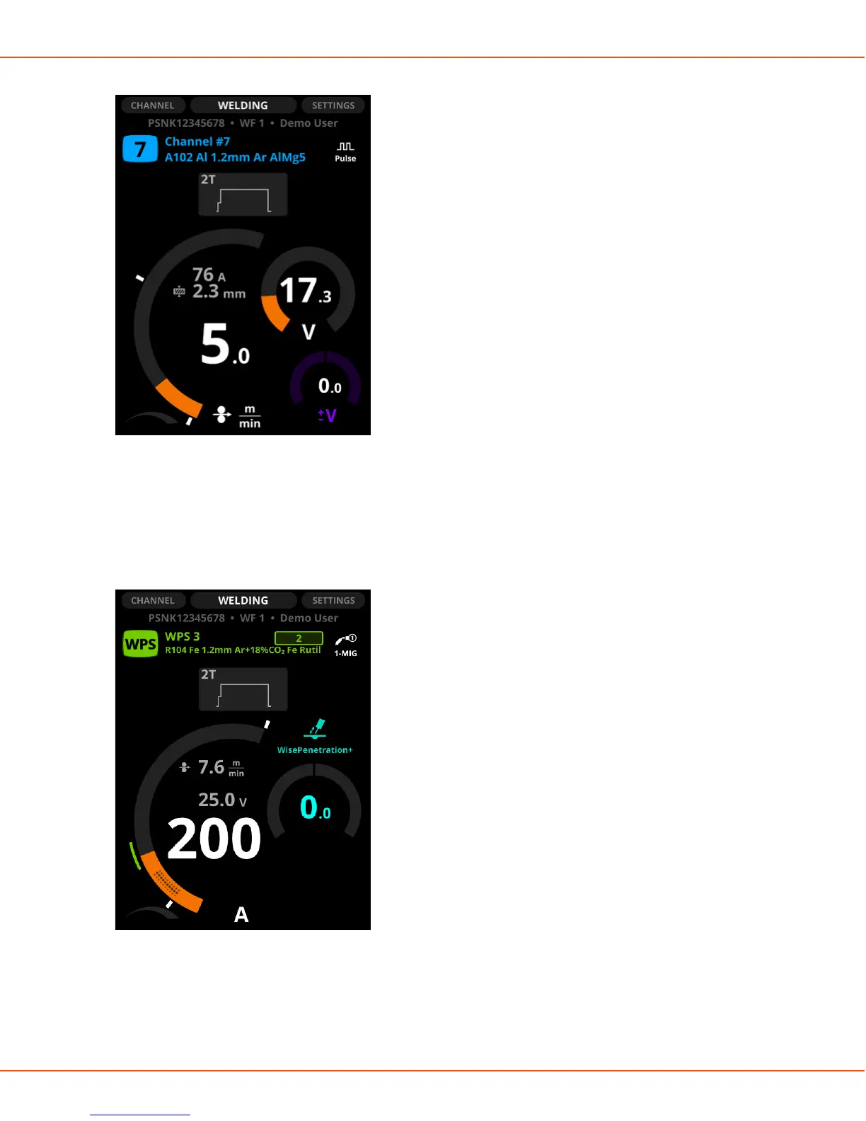
Figure 15: The minimum and maximum stoppers
The value range of the welding power and voltage graphs specified by the Welding Procedure
Specification (WPS) are displayed with a green arc between the stoppers. The stoppers are
by default at the top and bottom of the specified WPS area, but you can adjust them to your
preferences: to narrow the area or to weld outside the specified area.
Figure 16: The minimum and maximum stoppers for WPS
If you adjust the wire feed speed or voltage to a level outside the WPS range, the parameter
graph turns red and a warning symbol appears on the display.
OPERATING MANUAL | EN 99
©
KEMPPI 2017 | 1817
 Loading...