142 Keysight PXIe Chassis Family User Guide
Chassis Maintenance Chassis Backplane Switches
Chassis Backplane Switches
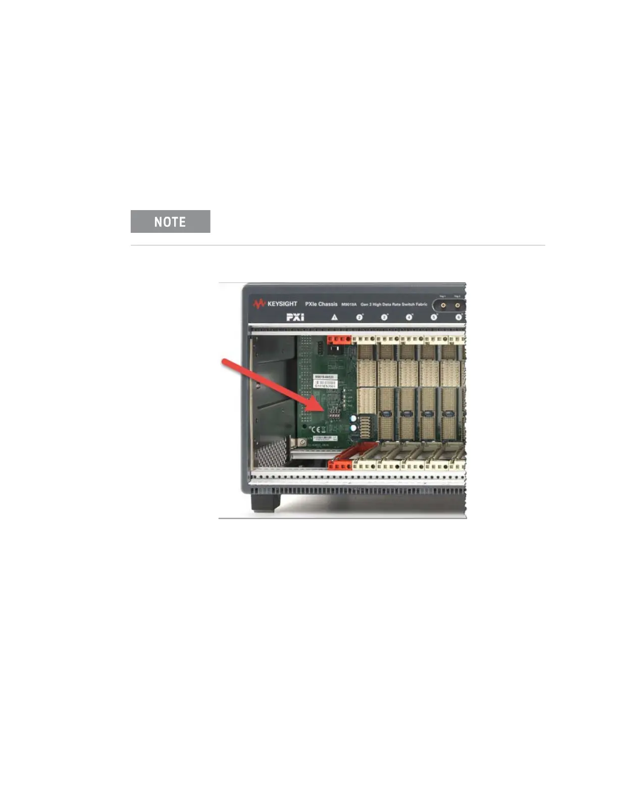
On the M9010A, M9018B, and M9019A chassis, just to the left of slot 1 (see
Figure 75 below), is a bank of four switches. The default setting for all four
switches is in the down position. For a detailed explanation of these switches,
refer to the Keysight PXIe Chassis Family Service Guide.
Here is a brief description of the switches (numbered left to right):
Switch # 1: FPGA image. This selects the chassis FPGA endpoint image. Golden
image (switch up) causes the chassis to boot to its failsafe image. The Default,
down, position causes the chassis to boot with its normal image.
Switch # 2: Fabric Selection Switch. This switch selects the PCIe fabric mode.
– On the M9010A and M9019A chassis: RST/Safe means that Gen 1-limited
fabric is selected on all slots and links. NORMal is Gen 3 mode.
– On the M9018B chassis, RST/Safe is used for an emergency reset to the
1x8 Gen 2. This is similar to the fabric pushbutton on the M9018A chassis.
For additional information, refer to “Restoring the Factory Default 1x8 Base
Configuration” on page 131.
These switches are for Keysight authorized service personnel only.
Figure 75 PXIe Chassis Backplane Switches