54 Keysight PXIe Chassis Family User Guide
Power Supply Operation Measuring the Main Voltage Rails Directly
Measuring the Main Voltage Rails Directly
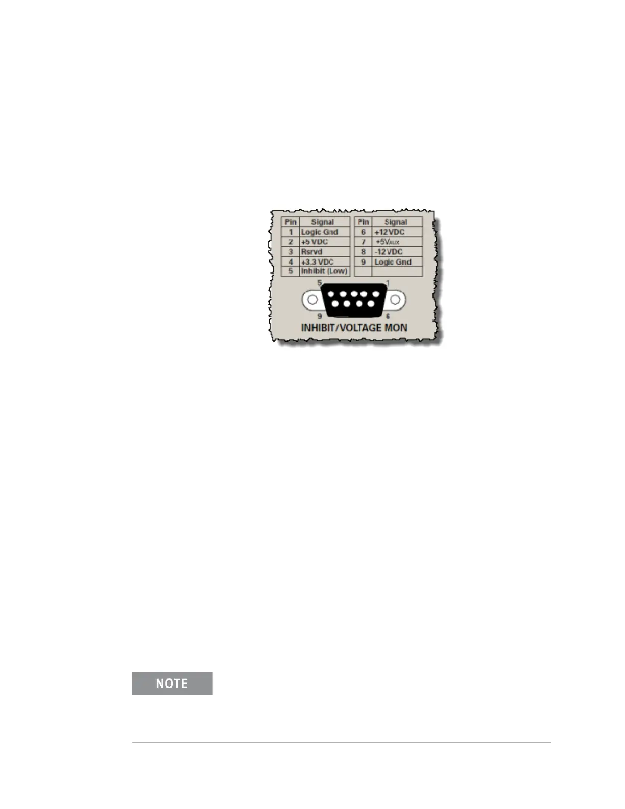
The five main voltage rails can be measured on the DB-9 connector on the
chassis rear panel using a digital multi-meter. The voltage rail pin assignments
are shown in the following image.
Each voltage rail contains a current limiting resistor to prevent accidentally
shorting the supplies
Monitoring the Power Supply Rails
The chassis allows you to monitor the following five power supply rails:
– +3.3V
– +5V
– +5V
aux
The 5 V
aux
cannot be monitored in the M9018A chassis SFP; it is
monitored in the PXIe Chassis Family SFP for the M9010A, M9018B, and
M9019A chassis. (Note: in the PXIe Chassis Family Soft Front Panel, the
+5V
aux
is shown as +5.0V_STANDBY).
– +12V
– –12V
The SFP and the chassis drivers can set voltage limits around the rails such that
an alarm will be generated if a rail voltage falls outside of the specified limits.
The front panel Power LED provides collective information about all five rails.
Figure 17 DB-9 Connector Pin-out from Chassis Rear Panel
In rare cases where the 5V
aux
is loaded to the point where it
deviates outside of the ±5% tolerance, it can cause the Power LED
to blink. Check the voltage or alarm in the Soft Front Panel (in the
PXIe Chassis Family SFP, this voltage is called the
+5.0V_STANDBY).