Keysight PXIe Chassis Family User Guide 89
Chassis Trigger Lines Configuring the PXI Trigger Bus
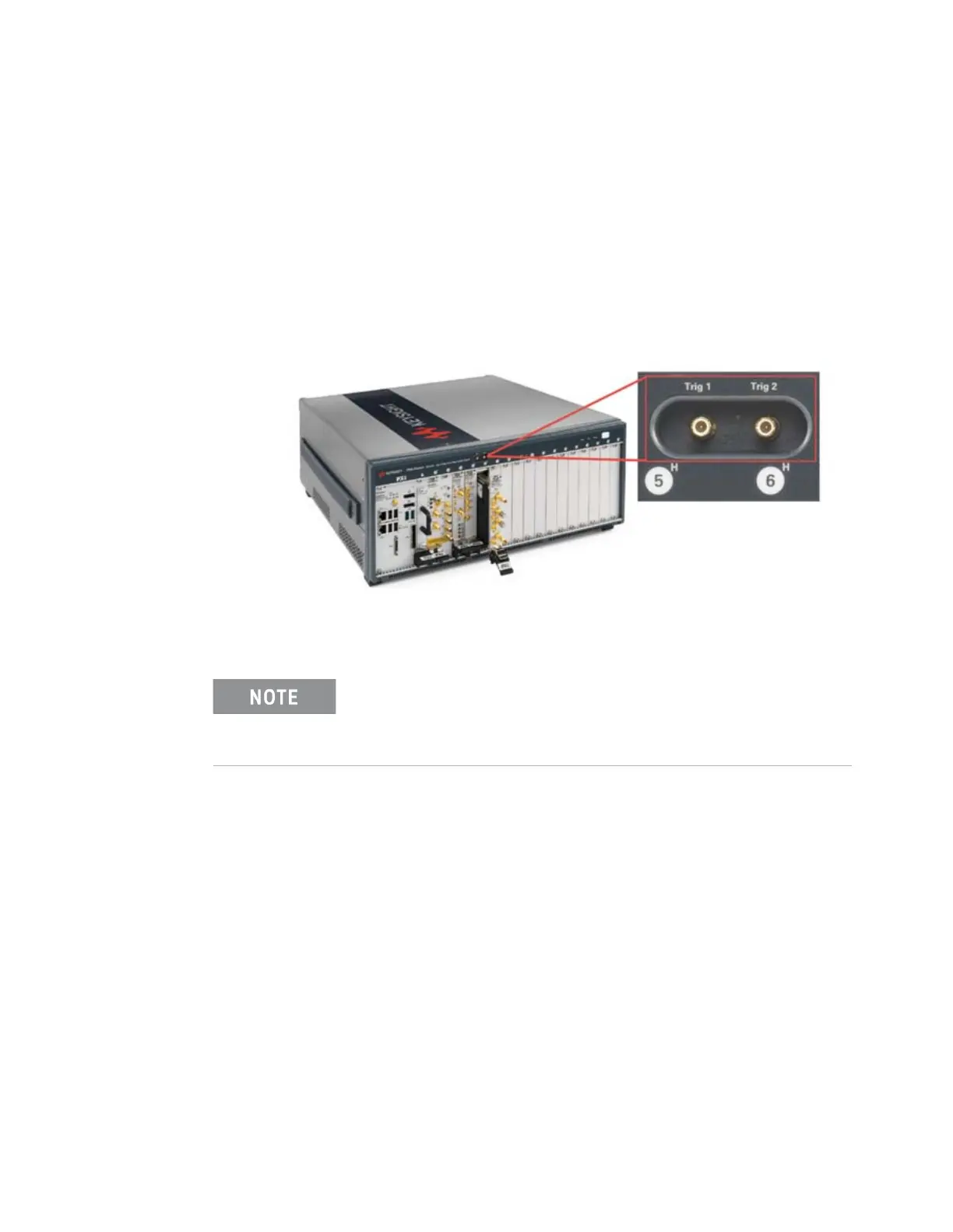
Front Panel Trigger Ports
In addition to the eight PXI trigger bus lines, the M9010A, M9018B and M9019A
chassis have two front panel 50 Ω SMB trigger connectors that you can assign to
any of the eight trigger lines of the PXI_TRIG [0:7] trigger bus.
These SMB trigger ports should be managed similarly to how PXI modules assert
or receive triggers on the trigger bus (see “Trigger Bus Segments” on page 85).
The M9010A 10-slot chassis backplane has two Trigger Bus Segments which are
numbered 1 and 2.
The M9018B and M9019A 18-slot chassis backplanes have three Trigger Bus
Segments which are numbered 1, 2, and 3.
Each front panel Trigger Port can be configured as Input or Output.
Trigger Port capability as a function of the firmware version
The front panel trigger port capability depends on the version of Trigger Bridge
firmware installed in your chassis. The Trigger Bridge firmware version 0, from
the 2017 firmware package, has less capability than the later version found in the
2018 firmware package. See “Updating Chassis Firmware” for instructions on
looking up your firmware version and updating the firmware.
Figure 41 Chassis Front Panel Trigger Ports (M9019A chassis shown)
Make certain that your test application is not running when you
reconfigure these two trigger ports. Reconfiguring the ports from
input ports to output ports may cause unexpected noise on the
trigger port lines at the moment you make the change.