60 Keysight PXIe Chassis Family User Guide
Chassis Cooling and Rack Mounting
– A minimum of 50 mm (2 inches) of clearance should be provided in the
front, rear, top and sides of the chassis for ventilation. Depending on
module power consumption, clearance may also be needed below the
chassis to accommodate the air intakes on the bottom of the chassis. This
is discussed further in the next section.
– The fans can either be set to operate at maximum speed, or can be set so
that the fan speeds are a function of the chassis temperature. With the
latter capability, you can specify the fan speed vs. temperature profile
using either the Soft Front Panel (SFP) or programmatically using the IVI
drivers.
– The M9018B and M9019A chassis have eight temperature sensors, and the
M9010A has five sensors mounted to the top of the backplane to monitor
the air flow temperature downstream from the modules. These
temperatures can be read using the SFP or programmatically.
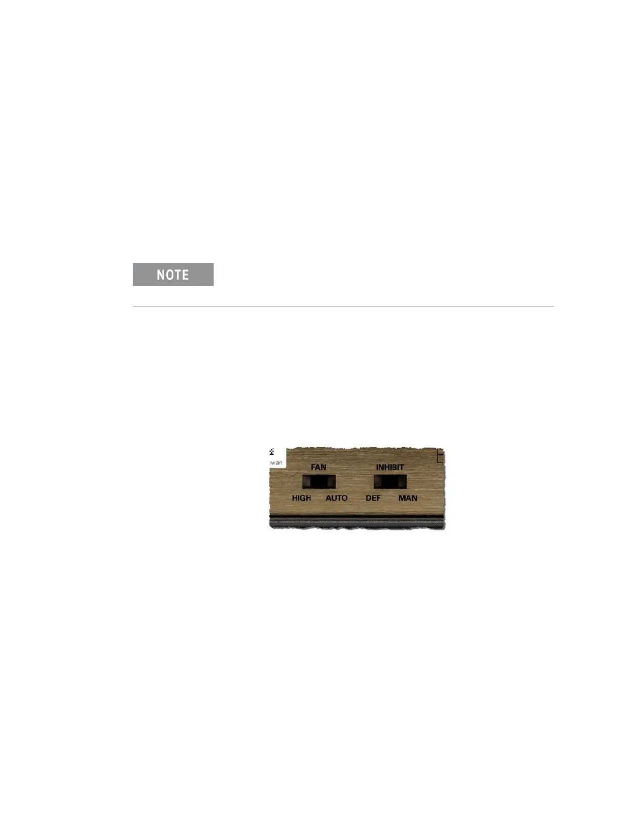
– Ensure that the chassis Fan switch (on the chassis rear panel) is set to
AUTO and the Inhibit switch is set to DEF.
– Position the chassis to provide ample space around the chassis fan intake
and exhaust vents. Blockage by walls or obstructions affects the airflow
needed for cooling.
If a fan stops completely, the chassis shuts down. Determine th
cause of the fan stopping (obstruction, fan failed etc.) and correct it
before powering on the chassis.
Chassis Rear Panel Fan and Inhibit Switches