TS-5020 Automotive Electronics Functional Test System Wiring Guide and Hardware Reference vii
List of Figures
1 Legal Information
2 Safety and Regulatory Information
3 System Overview
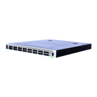
Figure 3-1. Express Connect Test System Interface TC1 Through TC4 3-7
Figure 3-2. Express Connect Test system Interface TC1 Through TC8 3-8
Figure 3-3. Macpanel L2000 (TITAN) Test System Interface 3-10
Figure 3-4. Typical TS-5020 System Rack with Express Connect Layout 3-28
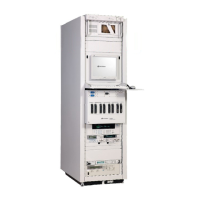
Figure 3-5. Typical TS-5020 System with L2000 (TITAN) test interface 3-29
Figure 3-6. TS-5020 Simplified System with Express Connect Block Diagram 3-30
Figure 3-7. TS-5020 Simplified System with L2000 (TITAN) Block Diagram 3-31
Figure 3-8. Rear View Of 34980A Multifunction Switch / Measure Unit 3-32
Figure 3-9. Cut-out View of Slot 4 with Terminal Card To Create Instument/Pin
Matrix 3-33
Figure 3-10. Multiple 34933A configured as Instrumentation and Pin Matrix 3-34
Figure 3-11. Multiple 34934A configured as Instrumentation and Pin Matrix 3-35
4 System Interconnects
Figure 4-1. TC1-TC4 Connector Keying 4-2
Figure 4-2. TC1-TC8 Connector Key Configuration 4-2
Figure 4-3. Crimping Wires to Contacts 4-4
Figure 4-4. Assembling TC1 to TC4 4-5
Figure 4-5. Connecting To The Test System Interface 4-6
Figure 4-6. Adding A Grounding Strap To Reduce ESD 4-7
Figure 4-7. Wrist Strap ESD Connector 4-8
Figure 4-8. Removing A Test Connector Contact 4-8
Figure 4-9. TC1 Pinouts 4-11
Figure 4-10. TC2 Pinouts 4-12
Figure 4-11. TCn Pin Assignments 4-13
Figure 4-12. TCn+1 Pin Assignments 4-14
Figure 4-13. PCA Layout For Full Profile Express Connect (For TC1-TC8 Use) 4-15
Figure 4-14. View of Full Profile Express Connect PC Assembly (2 of 4 possible PC
Assembly shown) 4-16
Figure 4-15. PCA Layout For Low Profile Express Connect (For TC1-TC4 Use) 4-17
Figure 4-16. TS-5020 System Connector (J6 or J60) TC1 and TC2 Assignments 4-18
Figure 4-17. TS-5020 System Connector (J6 or J60) TCn Assignments 4-19
Figure 4-18. TS-5020 Configuration Connector (J7 or J40) 4-20
Figure 4-20. Recommended System Grounding 4-22