66
Making Distortion Measurements
Identifying Analyzer Generated Distortion
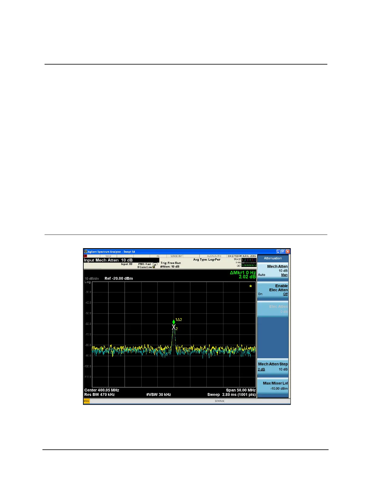
11 Increase the RF
attenuation to 10 dB.
• Press AMPTD Y Scale,
Attenuation, 10, dB.
Notice the ΔMkr1 amplitude
reading. This is the difference in
the distortion product amplitude
readings between 0 dB and
10 dB input attenuation settings.
If the ΔMkr1 amplitude absolute
value is approximately ≥1 dB for
an input attenuator change of
10 dB, the distortion is being
generated, at least in part, by the
analyzer. In this case more input
attenuation is necessary.
Increase the input attenuation
until ΔMkr1 amplitude stops
increasing or decreasing in value.
Return to the previous attenuator
step and the input signal
distortion measured will be
minimally impacted by the
analyzer internally generated
distortion. See Figure 6-2.
Figure 6-2 RF Attenuation of 10 dB
Step Action Notes

 Loading...


