PCR-M 27
Chapter 2 Installation and Preparation
1.
Check that the AC power supply meets the nominal input rating of the
PCR1000M / PCR2000M.
The voltage that can be applied is any of the nominal power supply voltages in the
range of 100 Vac to 120 Vac or 200 Vac to 240 Vac. The frequency is 50 Hz or 60 Hz.
• If the voltage distortion of the AC power line is large, it can lead to
malfunction. The PCR-M cannot be connected to a generator or a similar
device.
2.
Turn off the POWER switch.
3.
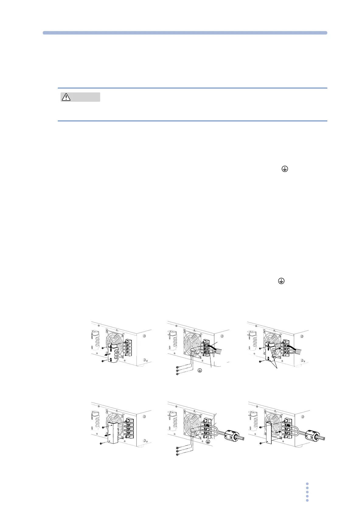
Remove the terminal cover that is attached to the AC INPUT terminal
block.
4.
Securely connect the power cord to match the L, N, and (GND) of the
AC INPUT terminal block.
5.
Put the terminal cover back to the terminal block that you removed in
procedure 3 .
For PCR1000M, use holes on lower side to attach the terminal cover.
6.
Attach crimp terminals to the switchboard end of the power cord.
The switchboard end of the input power cable is not provided with terminals.
For termination, attach a crimp-style terminal to each wire that meets the terminal
screws of the switchboard to be connected, and then securely connect the wires to the
terminal screws. Connection must be performed by qualified personnel.
7.
Turn off the switchboard.
8.
Connect the power cord to match the L, N, and (GND) of the
switchboard.
Fig.2-6 Connecting to the AC INPUT terminal block
CAUTION
L(black or
brown)
L(black or
brown)
N(white or
blue)
N(white or
blue)
(green or
green/yellow)
( green or
green/yellow)
PCR1000M
PCR2000M
3
4
5
3
4
5
Use the
lower holes.