86 PCR-M
Appendix
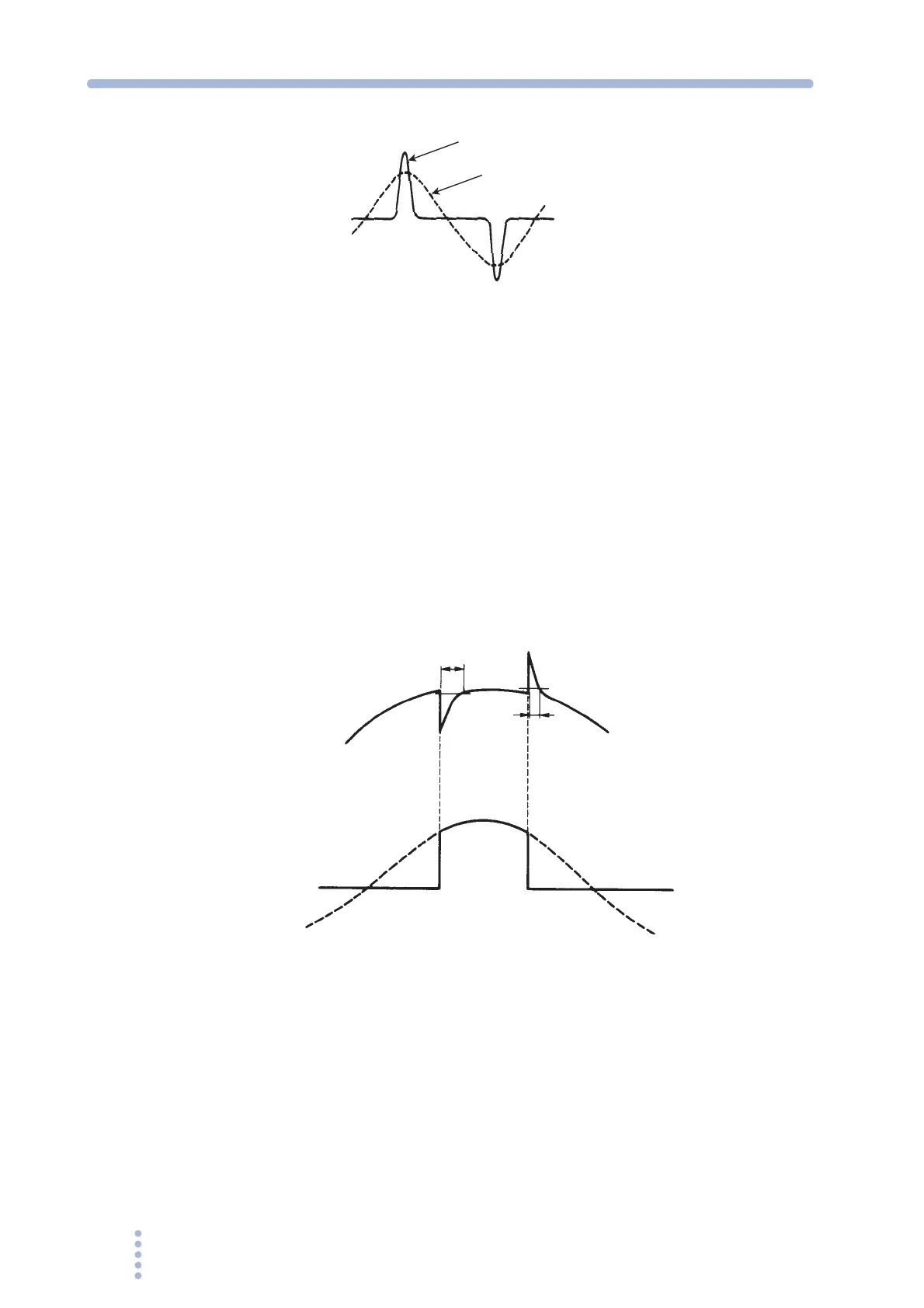
Fig.A-6 Output current waveform example
Output voltage waveform distortion ratio
The total harmonic distortion factor (%) of the output voltage waveform when the
output voltage is 50 V to 135 V (for the 135 V range) or 100 V to 270 V (for the 270
V range) and the load power factor is 1.
Output voltage response time
The time (unit: μs) for the output voltage change to exceed 10 % of the overall
change and return within 10 % of the overall change, when the output current
percentage is changed from 0 % to 100 % given that the output voltage is 100 V (for
the 135 V range) or 200 V (for the 270 V range) and the load power factor is 1 (in
the AC mode).
Fig.A-7 Output voltage response time
Capacitor-input rectifying load
Resistive load
Output voltage
Output current
t (
μ
s)
t (
μ
s)