PLZ-U Appendix A-5
If the function for turning off the load when the OPP trips is on, the load is turned
off.
If the function for turning off the load when the OPP trips is off (set to limit), the
PLZ-U supplies current as a constant power load at point B. Even if you attempt to
increase the input current by decreasing the resistance, the current is limited at point
B. If you decrease the input current by increasing the resistance, the OPP is cleared.
The PLZ-U returns to CR mode, and the operating point moves along segment AB.
Table A-2 Action taken when the OPP trips
■ Transition of the operating point: Overcurrent protection
(OCP)
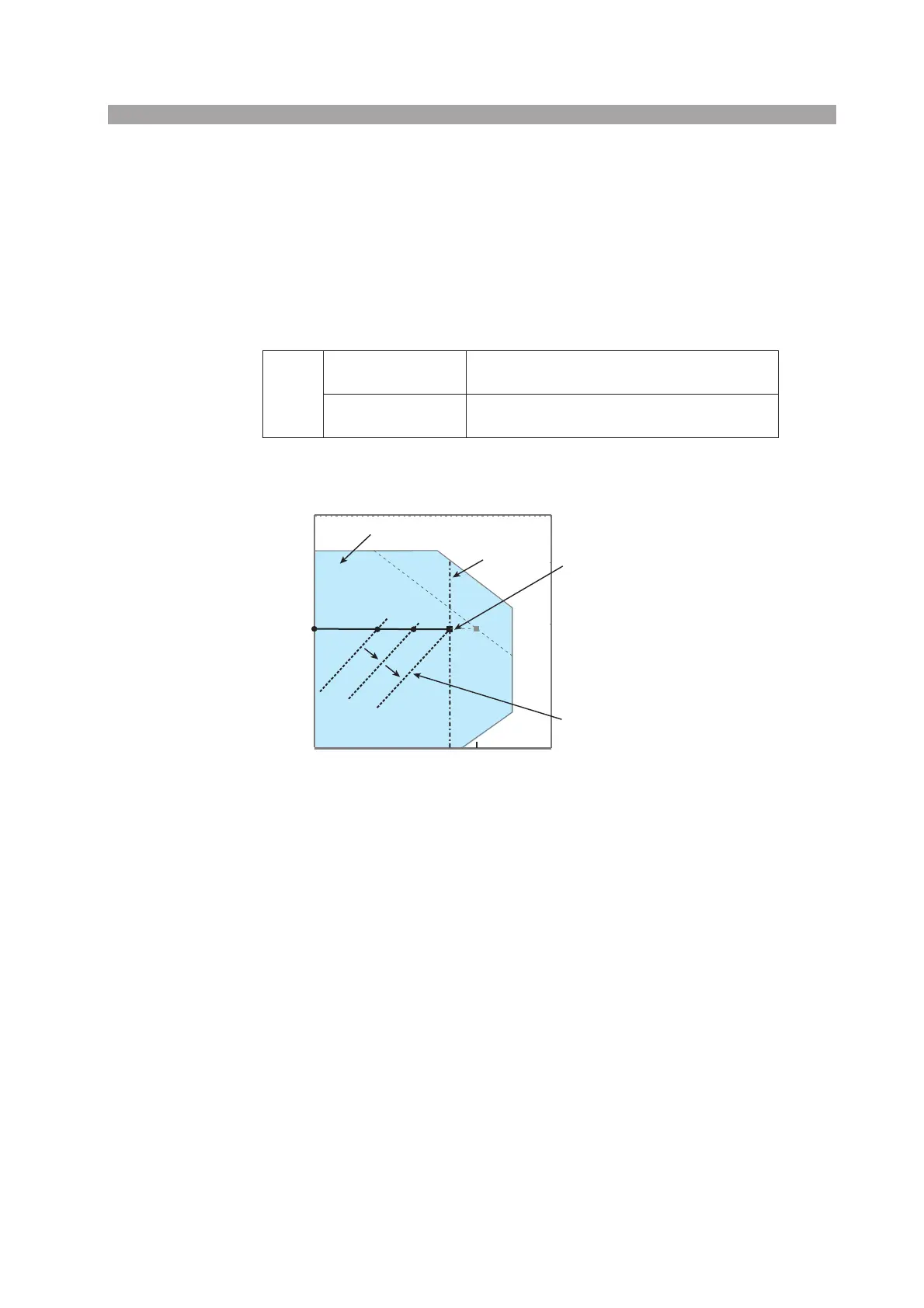
Fig. A-6 Transition of the operating point in CR mode (OCP trip point)
If the overcurrent protection (OCP) setting I
OCP
is less than the current value I
B
at
point B, when the PLZ-U resistance is decreased (R
1
→R
2
→R
F
) and the input cur-
rent (load current) is increased with the voltage of the constant-voltage power sup-
ply at V1, the operating point moves along segment AF (A
1
→A
2
→F). When point F
is reached, overcurrent protection (OCP) trips. At this point, two types of operation
are available on the PLZ-U depending on the protection action setting of the OCP.
If the function for turning off the load when the OCP trips is on, the load is turned
off.
If the function for turning off the load when the OCP trips is off (set to limit), the
PLZ-U supplies current as a constant current load at point L. Even if you attempt to
increase the input current by decreasing the resistance, the current is limited at point
F. If you decrease the input current by increasing the resistance, the OCP is cleared.
The PLZ-U returns to CR mode, and the operating point moves along segment AF.
Point B
Load-off function
on
Turns off the load (stops the current supply).
The PLZ-U no longer operates as a load.
Load-off function
off (limit)
CR mode ends. OPP continues, and the PLZ-U
supplies current as a constant power load.
Input current [A]
Input voltage [V]
Logarithmic scale
V1
A
B
Operating area
OCP trip point
Constant resistance line
(Constant resistance settings:
R
1, R2, and RF)
I
BIOCP
A1
A2
R1
R2
RF
F
Constant current line
(OCP setting)

 Loading...