PLZ-U Application Operation 5-21
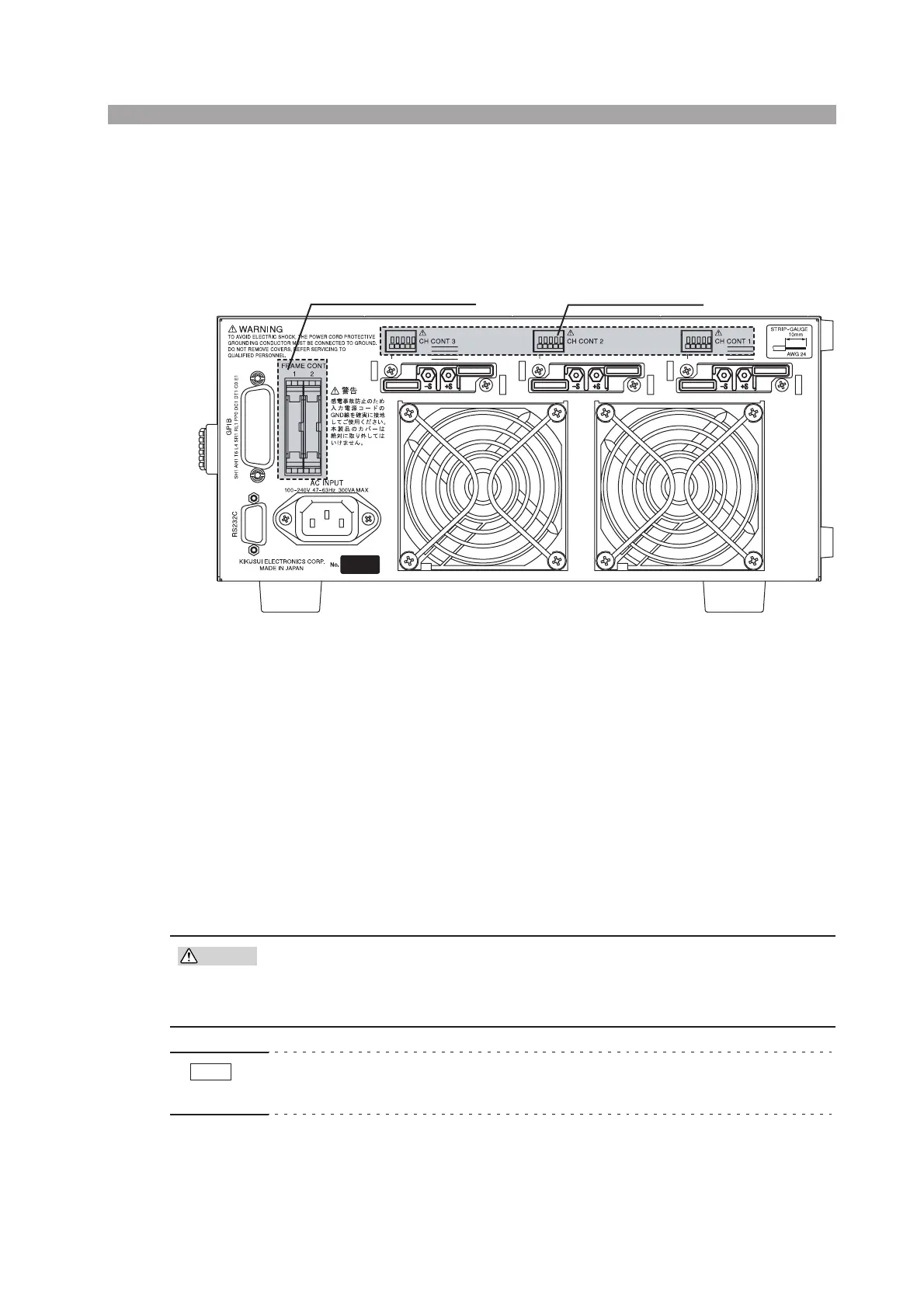
5.10 External Control
There are two methods of external control. One method is by using the FRAME
CONT connector of the frame. The other is by using the CH CONT connector of the
channel.
Fig. 5-14 External control
5.10.1 FRAME CONT Connector
The FRAME CONT connector consists of connector 1 and connector 2. Connector
1 is used for external control and inter-frame control. Connector 2 is used for inter-
frame control.
You can recall ABC preset memories and setup memories and turn the load on/off.
The connector also provides status outputs for load-on and alarms.
Inter-frame control is used by connecting multiple frames. From a single frame, you
will be able to recall ABC preset memories and setup memories and turn the load
on/off. Both connectors are standard MIL 20-pin connectors. Table 5-4 shows the
pin arrangement of the connector.
• To disconnect the connector, release the lock levers located on either side.
• Be sure to turn off the POWER switch when attaching or removing the
connector.
• Be sure to use a flat cable with a strain relief. To press-fit discrete wires or flat
cables, be sure to use a dedicated tool.
FRAME CONT connector
CH CONT connector
CAUTION
NOTE

 Loading...