5-22 Application Operation PLZ-U
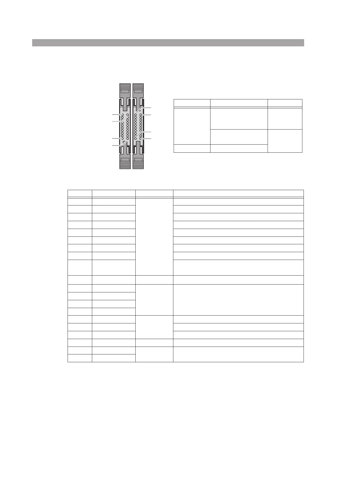
Table5-3 Pin numbers and compatible connectors
Table 5-4 Pin arrangement of connector 1
*1. Input: Low active, pulled up to 5 V through 10 kΩ (low level input voltage: 0 V to 1 V, high level input
voltage: 4 V to 5 V). The ENABLE pin is active at low level signal.
In the recalling of the ABC preset memories and setup memories, if multiple signals are set to low level,
the signal that is set to low level last is valid.
*2. When ENABLE is at high level, the following operations cannot be executed from the panel: recalling a
preset memory, recalling a setup memory, and turning the load on.
*3. Input: High active, pulled up to 5 V through 10 kΩ (low level input voltage: 0 V to 1 V, high level input
voltage: 4 V to 5 V). The ENABLE pin is active at low level signal.
*4. Output: Open drain, output withstand voltage of 30 VDC, output saturation voltage of approximately 0.7 V,
and maximum output current of 100 mA
Pin No.
Manufacturer Compatible Connector Note
Omron
XG5M-2032 or
XG5M-2035
XG5S-1001 (2 pcs.)
For discrete
wires
XG4M-2030
XG4T-2004
For flat
cables
KEL 6200-020-601
Pin No. Signal Name Input/Output Function
1A
Input
*1
Recall preset memory A of all channels simultaneously
2 B Recall preset memory B of all channels simultaneously
3 C Recall preset memory C of all channels simultaneously
4 AUX Reserved
5 MEM0 Recall the setup memory 0
6 MEM1 Recall the setup memory 1
7 MEM2 Recall the setup memory 2
8 MEM3 Recall the setup memory 3
9 ENABLE Enable the turning on/off of the load, recalling of presets
ABC, and recalling of setup memories 0 to 3.
*2
10 LOAD ON
Input
*3
Turn on the load on all channels simultaneously
11 N.C.
N.C. N.C.
12 N.C.
13 N.C.
14 N.C.
15 LOAD STATUS
Output
*4
Turns on when the load is on
16 ALARM STATUS Turns on when the alarm is activated
17 +5VIF 5 V and maximum output current of 100 mA
18 N.C. N.C. N.C.
19 GND
GND GND (chassis electric potential)
20 GND
1 2
1
1
2
2
19
20
20
19

 Loading...