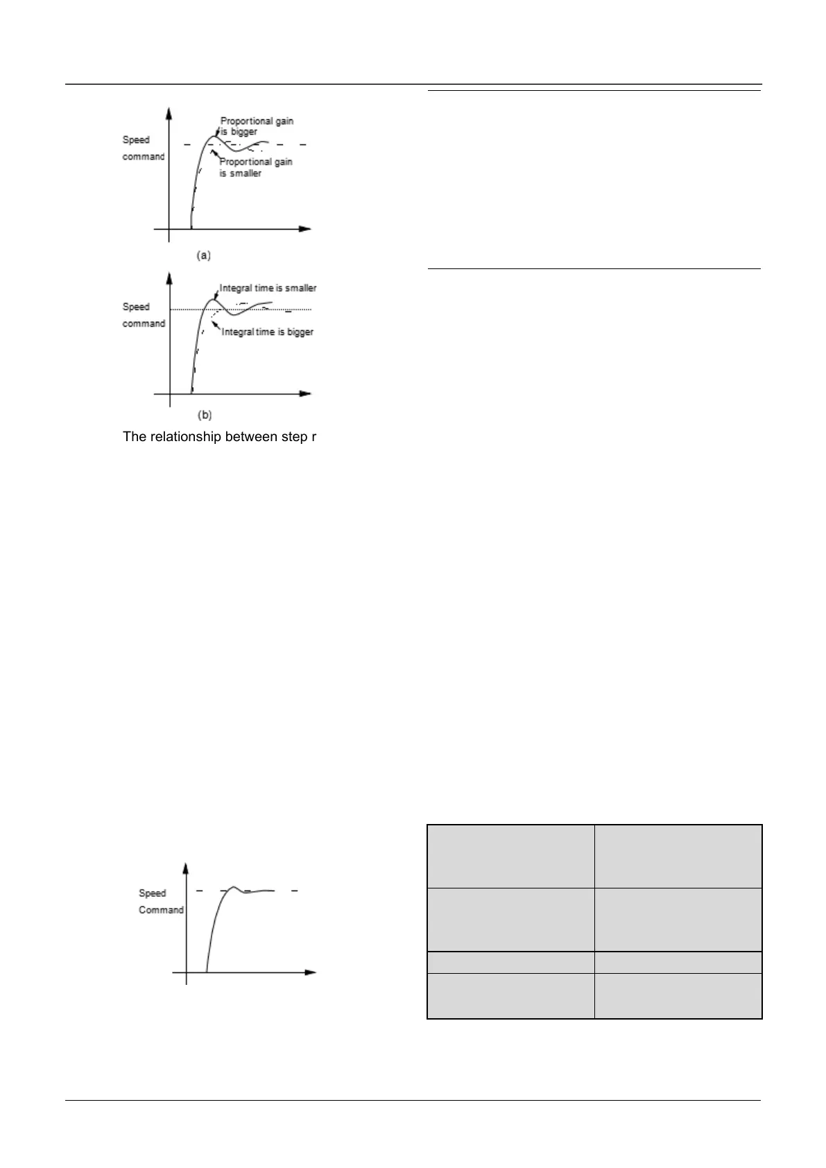
Fig.6-14 The relationship between step response and
PI parameters of speed regulator(ASR)
When increasing proportional gain P, it can speed
up the system’s dynamic response. But if P is too
big, the system will become oscillating.
When decreasing integral time I, it can speed up the
system’s dynamic response. But if I is too small, the
system will become overshoot and easily
oscillating.
Generally, to adjust proportional gain P firstly. The
value of P can be increased as big as possible if the
system don’t become oscillating. Then adjust
integral time to make the system with fast response
but small overshoot. The speed step response
curve of speed, when set a better value to P and I
parameters, is shown in Fig.6-15. (The speed
response curve can be observed by analog output
terminal AO1 and AO2,please refer to Group A6)
Fig.6-15 The step response with better dynamic
performance
Note:
If the PI parameters are set incorrectly, it will cause
over-voltage fault when the system is accelerated to
high speed quickly(If the system doesn’t connect
external braking resistor or braking unit),that is
because the energy return under the system’s
regenerative braking when the system is dropping
after speed overshoot. It can be avoided by
adjusting PI parameters
3. The PI parameters’ adjustment for speed
regulator (ASR) in the high/low speed running
occasion
To set the switching frequency of ASR (A5.07) if the
system requires fast response in high and low
speed running with load. Generally when the
system is running at a low frequency, user can
increase proportional gain P and decrease integral
time I if user wants to enhance the dynamic
response. The sequence for adjusting the
parameters of speed regulator is as following:
1)Select a suitable switching frequency( A5.07).
2)Adjust the proportional gain (A5.01) and integral
time(A5.02) when running at high speed,ensure the
system doesn’t become oscillating and the dynamic
response is good.
3)Adjust the proportional gain (A5.04) and integral
time(A5.05) when running at low speed, ensure the
system doesn’t become oscillating and the dynamic
response is good.
4. Get the reference torque current through a delay
filter for the output of speed regulator.A5.03 and
A5.06 are the time constant of output filter for ASR1
and ASR2.
 Loading...

