b1: pressure sensor (hPa - this sensor has to be configured between
analog channel 1 and analog channel 5, logger takes the first pressure
sensor on this range) -> 992 hPa
r1: radiation sensor (W/m
2
- this sensor has to be configured between
analog channel 1 and analog channel 5, logger takes the first radiation
sensor on this range) -> 1438 W/m
2
#t 14/11/24 15:38:34 $2E
If an anemometer were configured in anemometer channel 4, it would be
displayed after the radiation sensor (s4: anemometer 4 - 0.1 m/s scale):
#a s1=0 s2=39 s3=0 d1=886 d2=900 h1=58 t1=2950 b1=992 r1=1443 s4=0 $63
If a pluviometer were configured in anemometer channel 4, it would be
displayed after the radiation sensor (p1: pluviometer - 0.1 mm/s scale):
#a s1=0 s2=11 s3=0 d1=886 d2=900 h1=56 t1=2950 b1=992 r1=1440 p1=0 $4E
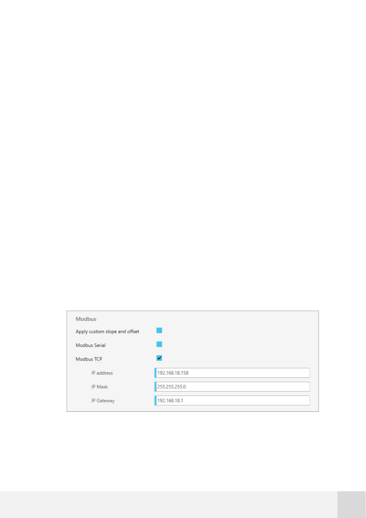
10.4 Modbus TCP
When using Modbus TCP, it’s necessary to set up the TCP parameters in Atlas software:
Fig. 76. Example configuration for Modbus TCP