Section 8
High Pressure Water System
20479291
2-2012/Rev 04
8-31
5. Loosen the cylinder head on the actuator. Unscrew and remove the actuator from the
valve body.
6. Unscrew the high pressure adapter and remove the adapter and valve seat.
7. Remove the stem, SST backup ring and brass backup ring from the valve body.
8. Remove the seal assembly by pushing it with the seal push tool (P/N 20470413). The
assembly must be pushed out through the actuator port in the top of the valve body.
9. Discard the stem, brass backup ring, seal assembly and valve seat.
10. Clean and inspect the valve body, being careful not to damage or scratch the bore.
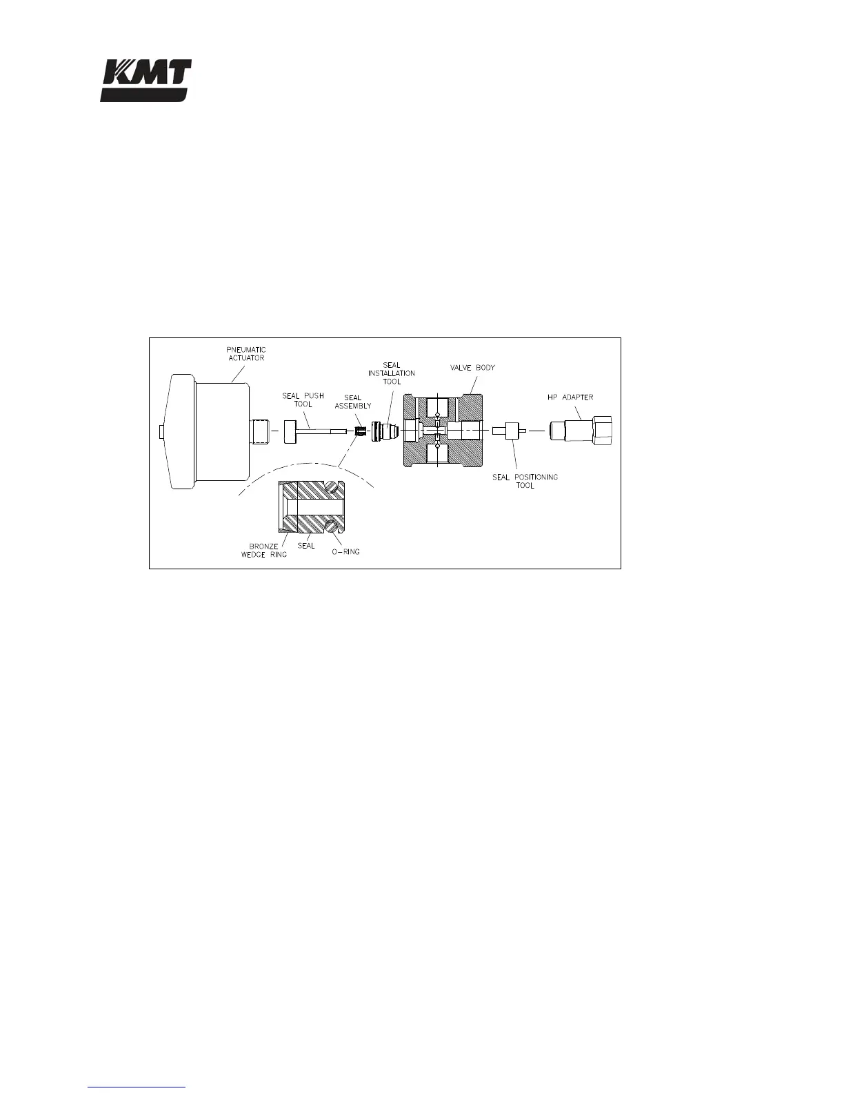
Figure 8-26: Valve Seal Installation
11. Place the seal positioning tool into the opposite end of the valve body as shown in Figure
8-26, Valve Seal Installation. Thread the high pressure adapter into the valve body until
light contact is made with the positioning tool. Tighten finger-tight only.
12. Apply Pure Goop anti-seize compound to the threads on the seal installation tool. Screw
the seal installation tool into the threads of the valve body. Tighten finger-tight only. See
Figure 8-26, Valve Seal Installation.
13. Lubricate the new seal and o-ring with FML-2 food grade grease. Insert the seal, o-ring
and bronze wedge ring into the seal installation tool, inserting the o-ring end of the seal
first so the tapered end of the seal (wedge ring end) faces the actuator. The tapered end of
the seal must face the actuator. See Figure 8-26, Valve Seal Installation.
14. Use the seal push tool to push the seal assembly into the bore of the valve body until the
seal makes light contact with the seal positioning tool.
15. Remove the push tool and the installation tool from the valve body.
16. Install the existing SST backup ring and a new brass backup ring on a new stem. The vee
groove on the SST backup ring must face toward the brass backup ring. The small OD of
the brass backup ring must face toward the seal assembly. See Figure 8-25, 3-Port Dump
Valve Components.
17. Apply FML-2 grease to the tip of the stem and insert the stem with the backup rings into
the top of the valve body so the stem enters the ID of the seal assembly. Insert the stem
until the chamfer on the stem is seated against the SST backup ring. See Figure 8-27,
Valve Stem Placement.
 Loading...