Section 6
Recirculation System
20412963
8-2012/Rev 07
6-3
NOTE
To conserve water usage it is recommended that the cooling water be shut off at
the end of the day. A sensor bulb from the modulating valve is submerged in the
reservoir. Even when the control power is off, the valve will remain open,
allowing water to flow until the oil is cooled.
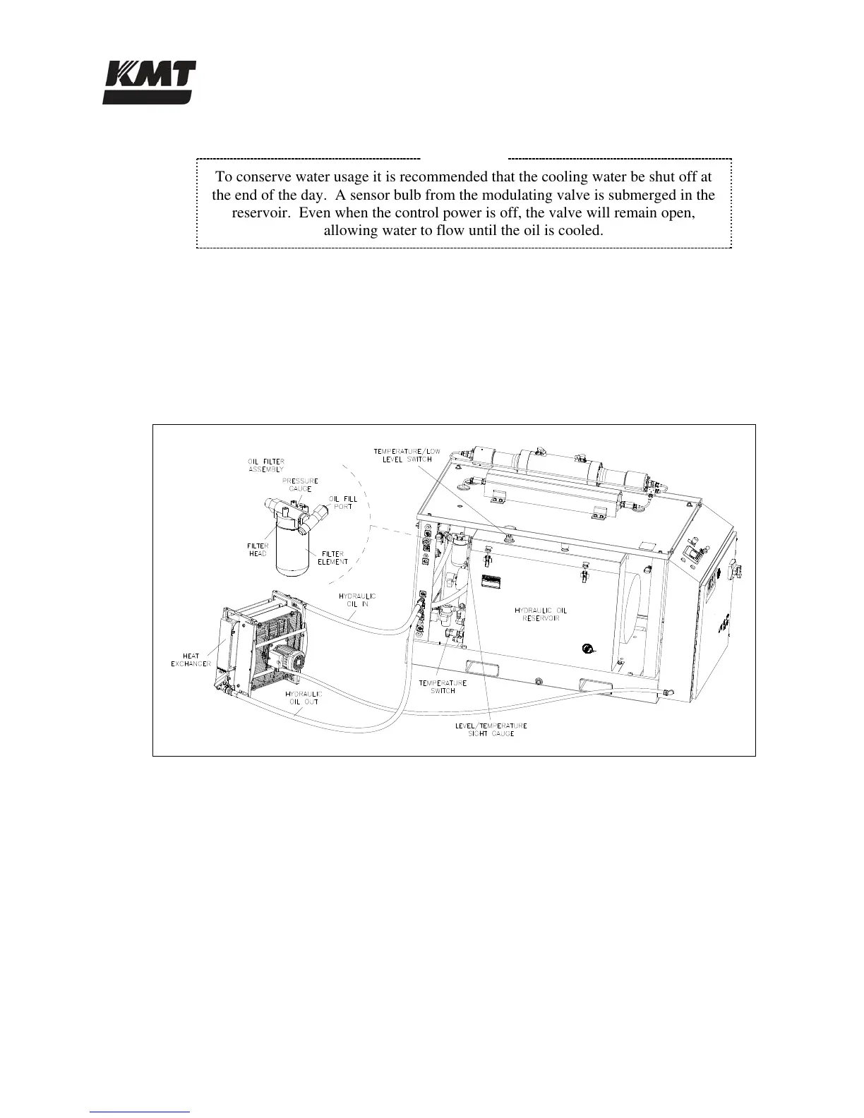
6.3 Operation (Oil-to-Air Models)
The recirculation pump pulls oil from the hydraulic oil reservoir and sends it to the external heat
exchanger. The oil-to-air heat exchanger controls heat build-up in the hydraulic oil. Oil
temperature can be visually monitored from a dual scale level/temperature sight gauge on the side
of the reservoir.
Figure 6-3: Recirculation System Components (Oil-to-Air)
The temperature switch mounted on the reservoir monitors the oil temperature and regulates the
air flow to the heat exchanger through a signal to the control panel to initiate power to the fan.
The cooled oil returns through the bulkhead, passes through the filter element and returns to the
reservoir.
The hydraulic oil filter assembly consists of the filter head, a filter element, pressure gauge or
indicator, bypass relief valve and the oil fill port. All 30, 50 and 60 horsepower machines are
equipped with a numeric pressure gauge that indicates inlet pressure. The filter element should
be changed when the gauge reads 40 psi (2.8 bar) at normal operating temperature. The 100
horsepower machines utilize a differential pressure indicator. The filter element on these
machines should be changed when the indicator enters the red zone at normal operating
temperature.

 Loading...